
Page 531 - Industrial Power Engineering and Applications Handbook
P. 531
Captive (emergency) power generation 16/505
the output voltage. as it will adjust only its operating p.f. a surge suppression device in the rectifier assembly to
(Section 16.9.1 B-2 and D-2). A difference in excitation protect against such voltage surges.
between the two machines when operating in parallel
will cause a circulating current I, (Figure 16.15). It will 16.6.2 Non-linear loads
add to one machine and subtract from the other, depending
upon which machine is relatively overexcited, compared Loads of rectifier, thyristor, UPS (uninterrupted power
to the other. The QDC, as discussed in Section 16.3.4, supply) and battery chargers etc.
will play the required role to limit the reactive loading of Fluorescent tube lights.
the two machines within permissible levels, when such a All such loads that have non-sinusoidal waveforms.
situation arises. All these loads cause a distortion in their pure sine
wave current waveforms. These distortions are termed
‘harmonics’ and such loads ‘non-linear loads’. Thyristor
16.6 Types of loads and rectifier loads fall into this category and affect the
sinusoidal waveform of the generator voltage and distort
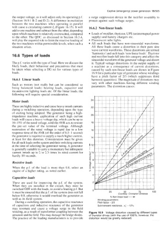
The p.f. varies with the type of load. Here we discuss the it. Typical voltage distortions in the output supply of
likely loads, their behaviour and precautions that must a machine as a consequence of current distortions,
be taken when selecting a DG set for various types of caused by such non-linear loads are shown in Figure
loads. 16.9 for a particular type of generator whose windings
have a pitch factor of 2/3 (which suppresses third
16.6.1 Linear loads harmonic quantities). The magnitude of distortions may
vary with other machines having different winding
Such as motors (not really but can be considered so parameters. The distortion causes:
being balanced loads) heating loads, capacitor and
incandescent lighting loads etc. Of the linear loads, the
following will require special consideration.
Motor loads
These are highly inductive and cause heavy inrush currents
during a switching operation, depending upon the type
of starting being adopted. The generator being a high-
impedance machine, application of such high current
loads will cause a heavy voltage dip, which can be up to
1 O-lS% of the rated voltage, until the AVR acts to restore
the pre-set value of the terminal voltage. Although
restoration of the rated voltage is rapid due to a low
response time of the AVR (of the order of 0.5-1 second)
the generator is required to supply a much higher current,
at least for this duration. Consideration must be given
for all such loads on the system and their switching currents
at the time of selecting the generator rating. A generator
is generally suitable to carry a momentary but infrequent
current inrush up to 2 to 2.5 times its rated current for
hardly 10 seconds.
Resistive loads
When the p.f. of the load is more than 0.8, select an
enginc of a higher rating, as noted earlier.
Capacitive loads
These are used for improving the p.f. of the system.
When they are installed in the circuit, they must be
% Non linear load -
switched OFF with the loads, to avoid a leading p.f. But U’
it must be ensured that the p.f. of the system does not fall 25 50 75 100
below 0.8, otherwise it would overload the generator as Courtesy: Crornpton Greaves
well as its field system. Winding parameters;
During a switching operation, the capacitive reactance Pitch factor - 2/3
of capacitors and inductive reactance of the generator Sub-transient reactance, x: - 12%
may resonate and cause a voltage surge in the field
winding, as a result of transformer coupling between the Figure 16.9 Voltage distortion caused by different types
armature and the field. This may damage the bridge diodes. of thyristor drives (with the use of IGBTs, however, the
The practice of the leading manufacturers is to provide distortion would be greatly reduced)