
Page 526 - Industrial Power Engineering and Applications Handbook
P. 526
16/500 Industrial Power Engineering and Applications Handbook
16.3.1 Residual voltage for self-excitation
The armature of the machine will normally have a residual
of the engine voltage of around 8 V (for LT machines) across the
terminals when running at the synchronous speed. If not,
3 as when the generator is operated after a long shutdown,
2750 - a d.c. voltage of 12 V can be applied through a battery
P for a few seconds to obtain the required residual voltage.
8
16.3.2 Operating PF
Small generators such as those used for captive power
0 - 0 generation are seldom used as synchronous motors or
25 50 75 100
%Load --+ synchronous condensers. To save on the cost of machines
their field system is generally designed for 0.8 p.f. lagging,
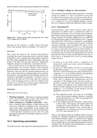
Figure 16.2 Typical speed-load characteristics of a 1500 unless designed for another application for a different
r.p.m. engine with 4% droop p.f. The generator output is also defined at 0.8 p.f. lagging
and rated in kVA. The 0.8 p.f. so selected is in consonance
with the average p.f. at which a power system would be
operation of the generator, a higher droop will mean operating generally. The maximum kW rating of the
better load sharing. Refer to Examples 16.2 and 16.3. machine is therefore defined by kVA x p.f. The operating
p.f. plays a vital role in the selection of the machine. It
Governor is desirable that the load which the generator may have
to feed has a p.f. of at least 0.8 lagging and more, but not
This senses the speed of the machine and performs beyond unity. The machine may not perform well at p.f.s
extremely fast and accurate adjustments in the fuel supply lower than it is designed for, as well as in the leading
to the PM. In turn it regulates the speed and the output of mode, because
the PM within predefined limits, depending upon the
droop of the PM. The governor may be a mechanical At lower p.f.s the field system is required to be
(manual), hydraulic or electronic (automatic) device. overexcited, which may cause excessive heating of
The governor can be set to make the machine run at a the field windings.
constant speed, even on load variations, with extremely At lower p.f.s the machine will deliver even less than
quick and almost instantaneous speed control, and thus the theoretical output (< &. V’ I. cos 6) due to higher
maintain a near-zero AN. In a parallel operation they can 12R losses, which will remain the same while the active
also control load sharing automatically and accurately. component (I. cos 4) will be reduced corresponding
Power grids, receiving power from different sources, are to the lower p.f. See also Section 23.3.
extremely susceptible to frequency variations. Even a In the leading mode the field system will be ineffective.
small Afof the order of 0.5 Hz, may cause the system to When this is required the manufacturer must be
trip. A fast-actuating governor with low response time consulted. In the leading mode when the machine is
(as low as 0.5 second) can overcome such a situation by suitable to operate such, the voltage will improve and
quickly regulating the speed of the PM. the machine will operate in the underexcited mode.
While the field winding will now be less stressed, the
Generator leading p.f. is not healthy for the machine and the
equipment connected on it because
These may be of two types:
(a) The capacitive mode will cause an overvoltage
1 Rotating armature These have a rotating armature across the machine windings during a switching
and a static field excitation system. The output from operation (Section 23.5.1) which may damage them
the armature is taken through the sliprings. particularly the end turns.
2 Static armature or brushless alternators These (b) In the leading mode the harmonics, when present
have a rotating field excitation system and are now in the system, will magnify and further distort the
used more commonly compared to the conventional voltage and current waveforms. The windings of
types noted above, particularly in the medium and the machine are therefore more stressed due to
large ratings. Both generators are self-excited and have such spurious overvoltages (vh). For vh, see Section
a self-regulated excitation system. For the main 23.5.2(A) and equation (23.1).
parameters and general operating conditions, refer to
BS 4999-140. Thus, in the leading mode the machine tends to become
unstable. It is therefore mandatory to operate the machine
well within its stability region, i.e. between 0.8 p.f. lagging
16.3 Operating parameters and unity, unless it is also designed for a leading mode.
Every machine has its own operating parameters as shown
in Figure 24.9. To obtain its best performance, it must be
The following are some important operating parameters: operated within these parameters.