
Page 527 - Industrial Power Engineering and Applications Handbook
P. 527
Captive (emergency) power generation 161501
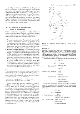
Generally, machines up to 1000 kVA are designed for Region '6'
these parameters. Generators used for hydropower ---+
generation and operating on smaller heads may also
sometimes be required to operate in a leading mode ab a
synchronous condenser to improve the p.f. of the system.
This may happen when the water head in the reservoir
falls below its minimum required level and is not capable
of generating the required minimum power. When used
in these conditions the field system has to be designed
for both lagging and leading modes.
16.3.3 A generator as a synchronous Low reactive ,/ 1,
motor or a condenser , power
When a generator is designed for a leading p.f. (in the Low active
underexcitation mode) it can operate as both a synchronous
motor and a synchronous condenser. The machine is now
self-starting and does not require a prime mover.
As a synchronous motor The machine is run primarily
to drive a mechanical load and is operated at the I,
synchronous speed and at unity p.f. The efficiency is Figure 16.3 Using a machine either as a motor or as a
now better than that of an induction motor. Except in condenser
assisting the system by consuming power at unity p.f.,
it does not help the system to improve its p.f.
As a synchronous condenser The machine is operated Example 16.1
Consider a process plant having a connected load of 15 000
without any mechanical loading. It is now used primarily kW and a running load of 12 500 h.p. at almost 0.65 p.f.
to supply leading reactive power to improve the system lagging. Let a few large induction motors aggregating 2000
p.f. The machine can now be operated with continuously h.p. be replaced by as many oversized synchronous machines,
variable leading reactive power, with the help of an with the purpose of improving the system p.f. in addition to
automatic voltage regulator (AVR) and a quadrature performing the motor's duties.
droop control (QDC), and can even improve a varying Considering an average efficiency of the induction motors as
p.f. of the system caused by fluctuating loads. The q = 92% and
machine can be made to operate up to 0.1 p.f. leading
(as a capacitor) without affecting its stability. The active p.f. = 0.9 lagging
power, however small, is delivered at 0.1 p.f. and is
consumed to feed its own no-load losses. Equivalent kW = 2ooo 0.746
0.92
= 1622 kW
Note
When de\ired, the machine can also be designed as an inductor to andkVA rating at 0.9 p.f. = -
1622
supply lagging reactive kVAr, with the help of AVR and QDC. It 0.9
will serve little purpose. if used both as a motor and a condenser. = 1802 kVA
Refer to Figure 16.3. illustrating the trajcclury of the current phasor,
I,. For the current I, at a p.f. cos I$ (leading), Reactive kVAr = 1802 sin cos-' 0.9
- Active power output per phase = V.fi cos I$. and = 1802 x 0.4359
~ Reactive power output per phase = V.li sin I$
= 785 kVAr (lagging)
We can observe that at higher leading p.f.s (region A For ease of illustration, all these parameters have been
in Figure 16.3), while the active power will rise, the drawn in the phasor diagram (Figure 16.4). To select the
reactive power will be too low to contribute effectively rating of the synchronous condensers, consider their average
towards the p.f. improvement of the system. This is also efficiency,
true at lower leading p.f.s (region B). While the reactive q = 95% and
power will now rise, the active power will be too low, to
perform any mechanical duty, the more so when part of p.f. = 0.3 leading
it will be consumed to feed its own no-load losses. The 1622
usual practice, therefore, is to use it either as a synchronous :. Total kVA rating = 0.95 x 0.3
motor (region A) or as a synchronous condenser (region = 5691 kVA. Say, 5700 kVA
B) at a time. Extra kVA can be built in to the machine
partly 10 irnprove the system p.f. and partly to perform and reactive kVAr = 5700 . sin cos-' 0.3
the required mechanical duty. The following example = 5700 x 0.95
will illustrate this. = 5415 kVAr (leading)