
Page 529 - Industrial Power Engineering and Applications Handbook
P. 529
Captive (emergency) power generation 16/503
through the armature windings when the two machines r---------~~~~~~~~-
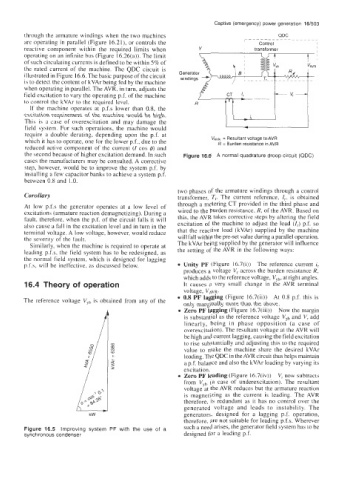
QDC
are operating in parallel (Figure 16.21), or controls the Control I
reactive component within the required limits when transformer I
operating on an infinite bus (Figure 16.26(a)). The limit
of such circulating currents is defined to be within 5% of
the rated current of the machine. The QDC circuit is
illustrated in Figure 16.6. The basic purpose of the circuit
is to detect the content of kVAr being fed by the machine
when operating in parallel. The AVR, in turn, adjusts the
field excitation to vary the operating p.f. of the machine
to control the kVAr to the required level.
If the machine operates at p.f.s lower than 0.8, the
excitation requirement of the machine would be high.
This is a case of overexcitation and may damage the -
field system. For such operations, the machine would I I
require a double derating, depending upon the p.f. at
which it has to operate, one for the lower p.f., due to the VnvR = Resultant voltage to AVR
R = Burden resistance in AVR
reduced active component of the current (I cos 4) and
the second because of higher excitation demand. In such Figure 16.6 A normal quadrature droop circuit (QDC)
cases the manufacturers may be consulted. A corrective
step, however, would be to improve the system p.f. by
installing a few capacitor banks to achieve a system p.f.
between 0.8 and 1.0.
two phases of the armature windings through a control
Corollary transformer, T,. The current reference, I,, is obtained
At low p.f.s the generator operates at a low level of through a metering CT provided in the third phase and
excitations (armature reaction demagnetizing). During a wired to the burden resistance, R, of the AVR. Based on
fault, therefore, when the p.f. of the circuit falls it will this, the AVR takes corrective steps by altering the field
also cause a fall in the excitation level and in turn in the excitation of the machine to adjust the load (I,) p.f. so
terminal voltage. A low voltage, however, would reduce that the reactive load (kVAr) supplied by the machine
the severity of the fault. will fall within the pre-set value during a parallel operation.
Similarly, when the machine is required to operate at The kVAr being supplied by the generator will influence
leading p.f.s, the field system has to be redesigned, as the setting of the AVR in the following ways:
the normal field system, which is designed for lagging
p.f.s, will be ineffective, as discussed below. Unity PF (Figure 16.7(i)) The reference current i,
produces a voltage V, across the burden resistance R,
which adds to the reference voltage, VYb, at right angles.
16.4 Theory of operation It causes a very small change in the AVR terminal
voltage, V,,,.
0.8 PF lagging (Figure 16.7(ii)) At 0.8 p.f. this is
The reference voltage Vyh is obtained from any of the
only marginally more than the above.
Zero PF lagging (Figure 16.7(iii)) Now the margin
is substantial as the reference voltage VYb and V, add
linearly, being in phase opposition (a case of
overexcitation). The resultant voltage at the AVR will
be high and current lagging, causing the field excitation
to rise substantially and adjusting this to the required
value to make the machine share the desired kVAr
loading. The QDC in the AVR circuit thus helps maintain
a p.f. balance and also the kVAr loading by varying its
excitation.
Zero PF leading (Figure 16.7(iv)) V, now subtracts
from VYb (a case of underexcitation). The resultant
voltage at the AVR reduces but the armature reaction
is magnetizing as the current is leading. The AVR
therefore, is redundant as it has no control over the
generated voltage and leads to instability. The
generators, designed for a lagging p.f. operation,
therefore, are not suitable for leading p.f.s. Wherever
Figure 16.5 Improving system PF with the use of a such a need arises, the generator field system has to be
synchronous condenser designed for a leading p.f.