
Page 546 - Industrial Power Engineering and Applications Handbook
P. 546
16/520 Industrial Power Engineering and Applications Handbook
the bus or vice versa. The machine will only float on \
the bus and the PM, will be supplying only the
mechanical losses, (Figure 16.24(c)).
D performance on-load
(Considering GI as the incoming machine and referring
to Figure 16.15)
1 By changing the driving torque or power input
Fixed parameters vb, fb, Z, = 0, and Z1
Variable parameters Zl and cos &, while El will have
a fixed magnitude but variable
phasor disposition.
When the power input to PMI is increased, the output
of GI increases. Since El is constant at a particular
excitation, it changes its phasor location only with
respect to V,. With a change in power input, therefore.
El traverses through a fixed trajectory as shown in
Figures 16.25 a and b, and with it changes its load
angle, el, load current, ZI and p.f. cos 4,. We have
considered four possible conditions, to define the
performance of the machine, under different levels of
power input:
When El is ahead of V, At a load angle 8, the
load current, 11, will lag vb by an angle 41 (refer to
Figure 16.25(a)). II is still considered to be lagging
Ef by almost 90", although it may be better on
load.
With the increase in the power input, E, will advance
further and improve its p.f. At one stage, the p.f.
will become unity and beyond this it will start leading
(Figure 16.25 (b)). Incidentally, the maximum p.f.
is achieved when the load angle el becomes 90",
which is also the limiting stage, beyond which it
would become an unstable region, as the exciter
would cease to exercise any control over the voltage.
At this point, refer to parameters E[, EA, I:, @{ and
e; as 90".
Any condition beyond unity p.f., i.e. GI > 0, would
mean ZI leading and can compensate the reactive
power of the system and improve its p.f. The machine
is now called a synchronous condenser (capacitor),
which besides supplying power to the main bus,
will also improve the system p.f. The above,
however, is only a theoretical analysis. A generator
designed for 0.8 p.f. lagging is not suitable to operate
at a leading p.f., as the excitation system would 11"
cease to exercise any control over the voltage. The (b)
voltage rises rapidly beyond unity p.f. as a result of
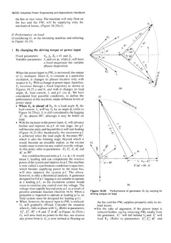
positive armature reaction (Section 16.4). When a Figure 16.25 Performance of generator GI by varying its
generator is required to operate at leading p.f.s, its driving torque on load
field system must be designed for leading p.f.s.
When, however, the power input to PMI is reduced, the bus and the PM, supplies primarily only its no-
GI will gradually offload. Consider the situation load losses.
when El, falls in phase with vb. (Refer to parameters For the sake of argument, if the power input is
E:, E,", 0: = 0 and I: at 4' in Figure 16.25(b).) reduced further, say by removing PMl totally from
GI will now feed no power to the bus, nor receive the generator, E;' will fall behind vb and I; will
any power from it. GI is now termed as floating on lead vb. (Refer to parameters E:, ET, e; and