
Page 550 - Industrial Power Engineering and Applications Handbook
P. 550
16/524 Industrial Power Engineering and Applications Handbook
second. For example, for a difference of 2 Hz the lamps Before closing the breaker it is also essential to know,
will flicker twice every second. whether the incoming machine was running a little too
In both the above cases the following will occur when fast or too slow. As discussed in method 5, the incoming
the generator breaker is closed and the frequency of the machine must run a little too fast compared to the machine
incoming machinefl is not equal to the frequency of the already running or the infinite bus while being
existing sourcefb. For ease of explanation, we consider synchronized. When so it will share a part of the existing
the dark lamp method. In the voltmeter method it is the load, no sooner it is synchronized and fulfils the purpose
voltrnekr needle that will flicker rather than the lights. for which it is being synchronized with the existing source.
To ascertain this before synchronizing, increase the speed
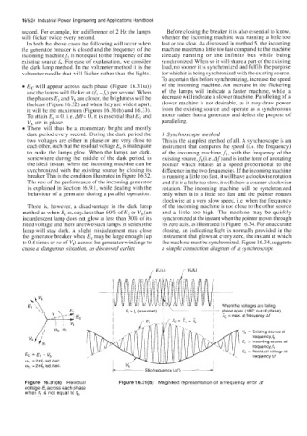
Ec will appear across each phase (Figure 16.31(a)) of the incoming machine. An increase in the flickering
and the lamps will flicker at (f, -fb) per second. When of the lamps will indicate a faster machine, while a
the phasors El and Vb are closer, the brightness will be decrease will indicate a slower machine. Paralleling of a
the least (Figure 16.32) and when they are widest apart, slower machine is not desirable, as it may draw power
it will be the maximum (Figures 16.31(b) and 16.33). from the existing source and operate as a synchronous
To attain E, = 0, i.e. A0 = 0, it is essential that E, and motor rather than a generator and defeat the purpose of
V, are in phase. paralleling.
There will thus be a momentary bright and mostly
dark period every second. During the dark period the 3 Synchroscope method
two voltages are either in phase or are very close to This is the simplest method of all. A synchroscope is an
each other, such that the residual voltage E, is inadequate instrument that compares the speed (Le. the frequency)
to make the lamps glow. When the lamps are dark, of the incoming machine,f,, with the frequency of the
somewhere during the middle of the dark period, is existing source,fb (Le. Af) and is in the form of a rotating
the ideal instant when the incoming machine can be pointer which rotates at a speed proportional to the
synchronized with the existing source by closing its difference in the two frequencies. If the incoming machine
breaker. This is the condition illustrated in Figure 16.32. is running a little too fast, it will have a clockwise rotation
The rest of the performance of the incoming generator and if it is a little too slow, it will show a counter-clockwise
is explained in Section 16.9.1, while dealing with the rotation. The incoming machine will be synchronized
behaviour of a generator during a parallel operation. only when it is a little too fast and the pointer rotates
clockwise at a very slow speed, i.e. when the frequency
There is, however, a disadvantage in the dark lamp of the incoming machine is too close to the other source
method as when E, is, say, less than-60% of E2 or V, (an and a little too high. The machine may be quickly
incandescent lamp does not glow at less than 30% of its synchronized at the instant when the pointer moves through
rated voltage and there are two such lamps in series) the its zero axis, as illustrated in Figure 16.34. For an accurate
lamp will stay dark. A slight misjudgement may close closing, an indicating light is normally provided in the
the generator breaker when E, may be large enough (up instrument that glows at every zero, the instant at which
to 0.6 times or so of vb) across the generator windings to the machine must be synchronized. Figure 16.34, suggests
cause a dangerous situation, as discussed earlier. a simple connection diagram of a synchroscope.
I When the voltages are falling
I i phase apart (180” out of phase),
fc = max at frequency Af
Vb = Existing source at
frequency, f,
,E1 = Incoming source at
\I II Iv” ‘4, - frequency Af
Figure 16.31(a) Residual Figure 16.31(b) Magnified representation of a frequency error Af
voltage ,Ec across each phase
when f, is not equal to fb