
Page 552 - Industrial Power Engineering and Applications Handbook
P. 552
16/526 Industrial Power Engineering and Applications Handbook
machine runs a little too slow it will fall behind the 1 As a frequency (AB comparator and frequency
existing source and operate as a synchronous motor, balancing or equalizing unit (FNI) This unit
drawing a reactive power from the existing source, rather compares the difference in the two frequencies (Af)
than feeding to it, and thus stress it further. Such a situation and controls it through an in-built frequency balancing
is undesirable as the incoming machine is being switched relay. The relay sends out a pulse to the motorized
on the system precisely to relieve the existing source of governor of PM,, (Figure 16.36) to raise or lower its
its overstress by sharing a part of its load. It is therefore speed to attain the pre-set AL within 0.15 Hz, depending
mandatory that the incoming machine must be running a upon the size of the machine and the flywheel used
little faster than the existing source at the instant of with the PM, The relay can be built into the auto-
synchronizing. When it is, the incoming machine will synchronizing relay or can be a separate unit.
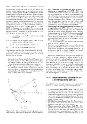
immediately share a part of the load equal to I, (Figure 2 As a voltage (AV) comparator and voltage balancing
16.35) to the extent it was too fast. The synchronizing or equalizing unit (UNI) This unit compares the
relays are provided with an inbuilt feature to accomplish difference in the two voltages (AV) and controls it
this requirement. (Also refer to Section 16.9.1(A1) and through an in-built voltage balancing relay. The relay
(Cl), Figures 16.16(a) and 16.22.) If sends out a pulse to the AVR of GI through a motorized
potentiometer, which can be introduced in the QDC
I, = circulating current (load on the incoming circuit (Figure 16.6) to raise or lower its excitation
machine) automatically to attain the pre-set AV, generally within
1, or Ib =loading on the existing source then the new I% of the rated voltage.
loading on the existing source, The relay can be built into the auto-synchronizing
relay or can be a separate unit.
1; = 7, - ?, in case of another machine G2 3 The auto-synchronizing relay monitors AV, Af and
or I( = ib - in case of an infinite bus phase shift (A@, between the two voltage phasors. In
other words it monitors the residual voltage, E,. It
The incoming machine can then be loaded as desired. also ensures that GI is slightly ahead of the existing
The total sequence of auto-synchronizing a standby source at the instant of synchronization.
generating unit with an existing system can thus be
summarized as follows: When these parameters are brought within the pre-set
values, the relay transmits a closing impulse to the
On receiving a closing signal, the AMF panel starts switching circuit of GI, a little in advance to account for
the prime mover of DC,. Through automatic speed the closing time of the breaker circuit. The breaker is
and voltage controls, as discussed in Section 16.7, GI thus switched at almost the same instant, when all the
is brought up to its speed and voltage as desired. parameters fall within the pre-set limits. The total closing
At this stage, an auto-synchronizing relay (Relay Code time may be a few ms (say, 150-300 ms), depending
25) is brought into the circuit. This relay is suitable upon the closing time of the breaker and any other coils
for any size of a generating unit to be synchronized or relays incorporated into the switching circuit which
automatically with another unit or an infinite bus. The may add to the closing time. (Also refer to Table 19.1,
relay executes three basic functions: for the closing time of breakers.)
16.1 1 Recommended protection for
a synchronizing scheme
In addition to the normal protection, as suggested in
Section 16.8.2 the following is also recommended:
1 A reverse power relay (RPR) (Relay Code 32) This
is meant for both active and reactive powers. If the
E2 or V, incoming machine is slow, it will operate as a
synchronous motor and draw power from the system
rather than feed it, not a desirable situation. The relay
will isolate the machine before it causes an overloading
of the existing source.
2 Field failure relay (Relay Code 40) This monitors
the exciter field current and detects the loss of field
supply or reduction in the field current.
3 Mains decoupling relay (Relay Code 78) This
protection is applicable when the captive generator is
hooked up with the main bus. The relay trips the
Figure 16.35 Sharing of load by an incoming machine during incoming breaker instantaneously on failure of the
synchronizing, when running faster than the existing source main supply. Otherwise on rapid restoration of the