
Page 548 - Industrial Power Engineering and Applications Handbook
P. 548
16/522 Industrial Power Engineering and Applications Handbook
B .. Hunting
Any error beyond permissible limits in AV, Af, or AB
may cause a shock and disturbance to the incoming
machine and the existing system. AB and Afmay cause
hunting which makes the rotor swing even beyond its
synchronous speed as a result of its own inertia. But this
develops an opposing torque too which retards these
overswings. Thus, while hunting would attenuate on its
Y own, the machine would supply and absorb large amounts
'vb
YI of power alternately during the course of hunting. As the
(a) (b) mechanical forces are proportional to the square of the
Phasor diagram of Phasor diagram of the
the existing source incoming generator current drawn by the machine at a particular instant (F 0~
12, equation (28.4)), they may be associated with large
current transients. The duration of such a situation would
play a very significant role in the stability of the system
and the safety of the incoming machine. This situation
must be dealt with as quickly as possible. Hence the
importance of keeping these variables as low as possible,
and reaching a stable state in only two or three cycles
after synchroniza-tion. Thus such reversals of mechanical
forces of the rotating masses are more important, rather
than the magnitudes of the torques that the machine will
vb El= VbandAV=O,AO=O have to sustain. In large power stations, where such forces
(c) may assume very high proportions, because of large sized
Both voltages in machines, they may even upset the normal supply system
phase and equal by severe power fluctuations, outage of the system or
overstressing of the incoming machine through its stator
and the rotor. For the significance of Afor AB refer to
Figures 16.31(a) and (b). To achieve the required
4 conditions of synchronization the following procedure
may be adopted.
To check the phase sequence
This can be checked with the help of a phase sequence
Phase displacement A8 indicator. This is a simple instrument that houses a small
causing residual voltage EC 3@ motor, which rotates a pointer connected to the motor
Time (wJ --C
through a gearbox. The direction of rotation of the pointer
El = El,,,. sin wit. and will determine the phase sequence of the system.
Vb = vb,,, sin @f.
o1 and wb are the angular speeds (2nf) To check the terminal voltage and frequency
in rad./sec. of the two voltages Figure 16.28 suggests a simple method to measure the
(4 terminal voltage El and the frequencyf, of the incoming
machine:
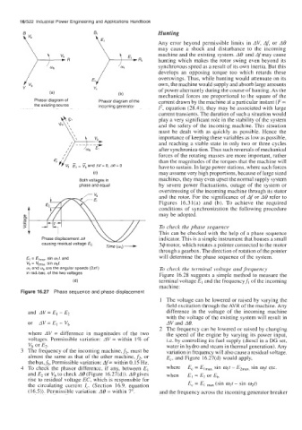
Figure 16.27 Phase sequence and phase displacement
1 The voltage can be lowered or raised by varying the
field excitation through the AVR of the machine. Any
and AV= El - E2 difference in the voltage of the incoming machine
with the voltage of the existing system will result in
or AV= E, - Vb AV and AB.
2 The frequency can he lowered or raised by changing
where AV = difference in magnitudes of the two the speed of the engine by varying its power input,
voltages. Permissible variation: AV = within 1% of i.e. by controlling its fuel supply (diesel in a DG set,
V, or E2. water in hydro and steam in thermal generation). Any
3 The frequency of the incoming machine,f,, must be variation in frequency will also cause a residual voltage,
almost the same as that of the other machine, f2, or E,, and Figure 16.27(d) would apply,
thebus,fb. Permissible variation: Af= within 0.15 Hz.
4 To check the phasor difference, if any, between E, where E, = Elmax, sin colt - E2max, sin Yt etc.
and E2 or vb to check AB (Figure 16.27(d)). A6 gives when EL = E2 or Eb
rise to residual voltage EC, which is responsible for
the circulating current I,. (Section 16.9, equation E, = El max (sin w,t - sin Yt)
(16.5)). Permissible variation: AB = within 7". and the frequency across the incoming generator breaker