
Page 544 - Industrial Power Engineering and Applications Handbook
P. 544
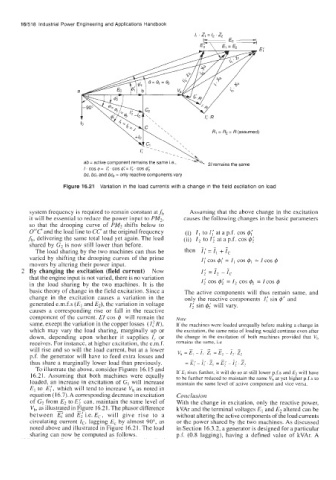
16/518  Industrial Power Engineering  and Applications Handbook
                                                            I,  . z, = /,   ' z,


                                  Y-'  '
                         IC                    '
                                                                 R, = R2 = R (assumed)
                                                     -.---*
                                                    \
                                                     \
                          ab = active component remains the same Le.,   21 remains the same
                          I. cos g= 1;. cos g;=  1;. cos g;
                          bc, bc, and bc, = only reactive components vary

                    Figure 16.21  Variation  in  the load currents with  a change in  the field excitation on  load


          system frequency is required to remain constant at fb   Asbuming  that the above change in the excitation
          it will be essential to reduce the power input to PM2,   causes the following changes in the basic parameters
          so  that  the  drooping  curve  of  PM2 shifts  below  to
          0°C'  and the load line to CC' at the original frequency   (i)  I, to Z; at a p.f. cos 4,'
          fb, delivering the same total  load yet again. The load   (ii)  l2 to 1; at a p.f.  cos @;
          shared by G2 is now still lower than before.
            The load sharing by the two machines can thus be   then  7; = 7, + 7,
          varied by  shifting the drooping curves of  the prime   I;cos@;=I, COSQ,  =IcosQ
          movers by altering their power input.
        2  By changing the excitation (field current)  Now    I;  = I, - r,
          that the engine input is not varied, there is no variation
          in  the  load  sharing by  the  two machines.  It  is  the   I; cos 4;  =I2 cos $2  = ICOS Q
          basic theory of change in the field excitation. Since a   The active components will thus remain  same, and
          change in  the  excitation  causes  a  variation  in  the   only the reactive components  I( sin 4'  and
          generated e.m.f.s (E, and E2), the variation in voltage   I; sin $2'  will  vary.
          causes  a  corresponding  rise  or  fall  in  the  reactive
          component of the current. EI cos Q will  remain the   Note
          same, except the variation in the copper losses (I,'R),   If the machines were loaded unequally before making a change in
          which  may vary  the load  sharing, marginally  up  or   the excitation, the same ratio of loading would continue even after
          down,  depending  upon  whether  it  supplies I,  or   the  change  in  the  excitation  of  both  machines  provided  that  V,
          receives. For instancc, at higher excitation, the e.m.f.   remains  the  same, i.e
          will  rise and so will the load current, but at a lower
          p.f. the generator will  have to feed extra losses and
          thus share a marginally lower load than previously.
            To illustrate the above, consider Figures  16.15 and
          16.21. Assuming  that  both  machines  were  equally   If E, rises further, it will do so at still lower p.f.s and El will have
                                                      to be further reduced to maintain the same V, at yet higher p.f.s to
          loaded, an increase in excitation of  G, will increase   maintain the  same level of active component and vice versa.
          E, to  E;, which will  tend to increase vh  as noted in
          equation (1 6.7). A corresponding decrease in excitation   Conclusion
          of C2 from E2 to E;  can, maintain the same level of   With the change in excitation, only the reactive power,
          vh, as illustrated in Figure 16.21. The phasor difference   kVAr and the terminal voltages El and E2 altered can be
          between  E,'  and E;  Le. E,,  will  give  rise  to  a   without altering the active components of the load currents
          circulating current I,-,  lagging  E,  by  almost 90°,  as   or the power shared by the two machines. As discussed
          noted above and illustrated in Figure 16.21. The load   in Section 16.3.2, a generator is designed for a particular
          sharing can now be computed as follows.     p.f.  (0.8 lagging),  having  a  defined  value  of  kVAr. A