
Page 549 - Industrial Power Engineering and Applications Handbook
P. 549
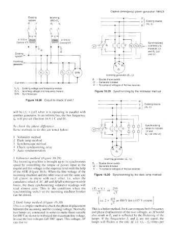
Captive (emergency) power generation  16/523
                                                                          .
                                                                          -
                  Existing     Incoming                                              Fl’i
                  system       MIGG,                                                    Existing source
                  R   Y        Rl   Y


            VillOV  laaaaal    w v,/110 v
           Control VT                Control VT                                          Synchronizing
                                                                                @J&&     voltmeters to
                                                                                         measure AV
                                                                                         and fc (A0
                                                                                         and Af)
          Common -                                              Incoming generator (E1, f,)
         Incoming
         generator-‘


                                                        Sl  - Double throw switch
                                                        0 - Generator breaker
                                                         V  - To compare voltages of the two sources
          Vb/fb  :  Existing voltage and frequency-meters
          €,if,  :  Incoming voltage and frequency-meters   Figure 16.29  Synchronizing by the voltmeter  method
          SYN  .  Synchroscope
                                                                         -
                Figure 16.28  Circuit to check  Vand f                -   T         R’i
                                                                    -                  Existing source

         will  be  (.f\  +f2)/2 when  it is operating in parallel with   T
         another generator. In an infinite bus, the bus frequency,
         fh,  will  prevail (Section  16.9.1 C and D).

         To check  the phase difference                                                Synchronizing
         Some methods to do this are noted below:                                      lamps to indicate
                                                                                       AVand
                                                                                       Ec  (A0 and Af)
         1  Voltmeter  method
         2  Dark  lamp method
         3  Synchroscope method
         1 Check synchronizing relay
         5  Auto synchroniration

         1  Voltineter method  (Figure 16.29)                  Incoming generator (E,, fl)
         The incoming machine is brought up to its synchronous   S,  - Double throw switch
         speed  by  controlling  the  torque  or power  input  to  the   0  - Generator breaker
         engine and the voltage to the required level with the help   V  - To compare voltages of the two sources
         of the AVR  (Figure  16.6). When the line voltage of the
         incoming machine and the other source are the same and   Figure 16.30  Synchronizing by the dark lamp method
         fall  almost  in  phase  with  each  other,  i.e.  when  the
         cumulative effect of AV, A0 and Affall within permissible
         limits, the three  synchronizing voltmeter  readings  will
         read  almost  zero.  This  is  the  condition  when  the
         synchronizing switch or the incoming machine breaker
         can be closed.
                                                                      or 480 V for a 4 IS V system  1
         2 Dork  lamp method  (Figure 16.30)
         This is a simpler method to check the phase displacement
         between the incoming and the existing voltage. Normally   This is a better method, for it can compare both frequency
         two lamps are connected in series to make them suitable   and phase displacement of the two voltages, as Af’wouid
         for 480 V as shown to withstand the maximum line voltage,   also result in E, and is reflected by  the flickering of the
         in case the two voltages fall  180” apart. This voltage, AV   lamps.  If  the  frequencies ,fl and fb are  not  equal,  the
         can rise to                                    lamps will  flicker at the rate Afi  i.e. (f,  -,fb)  times per