
Page 554 - Industrial Power Engineering and Applications Handbook
P. 554
16/528 Industrial Power Engineering and Applications Handbook
We will notice during our subsequent discussions that - Alarm
E and I cos @ are complementary. Although I and - Annunciation etc.
cos @cannot be altered directly, they are both functions Even the grounding of the generators can be monitored
of excitation voltage E. A variation in E will vary through this scheme, so that only one machine is
both I and cos@. The reactive or kVAr loading is thus grounded at a time, to avoid circulation of fault currents
dependent upon the voltage versus reactive load- (Section 20.10.1).
current characteristics of the generators and can be
varied through the QDC. Thus the power generated Example 16.2
or the load sharing by a generator can be altered in Consider two DG sets operating in parallel and having the
the following ways; following parameters:
Active power (kW) sharing By changing the
mechanical torque of the prime mover by changing G1 G2
its driving force (fuel supply).
Reactive power (kVAr) sharing By changing its Rating 750 kVA 750 kVA
p.f.
0.8 lagging
0.8 lagging
excitation (field current) that will alter the generated Speed at full load 1500 r.p.m. (50 Hz) 1500 r.p.m. (50 Hz)
e.m.f., E, in both magnitude and phase displacement, Droop 3 Yo 4 %
fremaining the same. A mismatch in excitation will
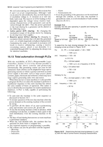
result in reactive unbalancing, causing a reactive To determine the load sharing between the two, draw the
circulating current, which is not desirable. It is drooping curves as shown in Figure 16.37.
controlled through QDC by adjusting the droop even
for identical machines. For G1: FF, = no-load speed = 1.03 x 1500
= 1545 r.p.m.
16.13 Total automation through PLCs and frequency = 1.03 x 50
or 51.5 Hz.
With the availability of PLCs (Programmable Logic FF, = full-load speed
Controllers, Section 13.2.3) it has become possible to = 1500 r.p.m. at a frequency of 50 Hz.
perform all the above controls and protections
automatically. The generating station can even be left FDA, = full active load
unmanned. Such schemes can be adopted for large captive = 750 x 0.8
generating stations or where a quicker and more accurate = 600 kW
power supply is desirable, such as large process plants
(cement, paper, chemicals and refineries) which may have Similarly for G2:
large captive generating units (two and more). FF, = no-load speed = 1.04 x 1500
When there are two or more machines it is also possible
to program the PLCs to select the machine to perform in = 1560 r.p.m.
a particular sequence so that each machine has almost and frequency = 1.04 x 50
the same number of hours of operation. This makes it = 52 HZ
easy to identify the next machine for routine maintenance
shutdown. A PLC is fully capable of performing the
following;
To auto-start the machine in the same sequence as e
discussed in Section 16.7.
To initiate operation of the next due machine when the
power demand on the existing machine or bus exceeds 52 Hz
its rating.
To perform all the duties of an auto-synchronizing
relay and monitor and correct AV, Afand A@.
To run the incoming machine a little in advance, while
switching it on the bus, to enable it share a part of the
load immediately from the existing machine or the
bus.
The duty of load sharing between two or more machines
is performed similarly.
-
When the load demand falls, the machine that has
operated for more hours is stopped first. 600 400 200 , 200 400 600
Any required sequence or programming is possible. kW kW
The scheme can also be provided with the required u Gi
G2
- Metering
- Protection Figure 16.37 Determining the load sharing between G1 and
- Indication G2 with the help of prime-movers drooping characteristics