
Page 551 - Industrial Power Engineering and Applications Handbook
P. 551
Captive (emergency) power generation 16/525
4 Check synchronizing reluy (Relq Code 25)
The purpose of this relay is to check the accuracy of
manual synchronizing. It basically checks Af, AVand A0
between GI and the existing source, as is done by a
synchronizing monitoring relay. When the quantities fall
within the permissible limits, the relay unlocks the G,
breaker and only then may the machine be synchronized
manually. It is a preferred practice to use such a relay as
a safety precaution for manual synchronizing, to double-
check the pre-set quantities of Afi AV and A0, to prevent
-- inadvertent synchronization, particularly because of the
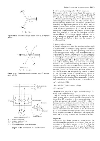
Ec= El - v, =o lead time required to close the breaker after a closing
impulse (Table 19.1), which a manual mode may not be
Figure 16.32 Residual voltage is zero when El is in phase able to assess so accurately and the machine may be
with V, synchronized just before or just after the moment of
synchronization.
5 Auto-svnchr~nizatiolz~i~uti~i~
In the preceding text we have discussed manual methods
of synchronizing two sources, more common for smaller
installations, say, up to 500 kVA. For large installations
and power generating stations such procedures may not
be practical for manual methods may not be so accurate
at the instant of synchronization. They are therefore likely
to cause a fault condition due to heavy circulating currents,
as a result of higher A0 or Af than permissible. It may
also lead to hunting. They are also time consuming.
Moreover, the synchronization may be required at times
when the operator is not available. For such installations,
When El = V, an auto-synchronizing scheme must be used. This will
comparef, and E, of the incoming machine with that of
Ec = E, + rb = 2Vb
the existing source and automatically control its speed
Figure 16.33 Residual voltage is maximum when El is phase VI) and excitation voltage (E,) to the pre-set values, so
apart with V, that AJ AV and A0 are within the permissible limits at
the instant of synchronization. The recommended limits for
such parameters, as noted above, may be considered as
AF = within 0.15 Hz
AV = within 1 c/r of the rated voltage
AQ* = within 7"
(*Both of these give rise to higher residual voltage, E(..
which may lead to hunting).
All this can be achieved with the help of an auto-
synchronizing relay, which is capable of monitoring the
phase shift, A@, to perform perfect synchronization even
without an operator. A normally open (NO) contact of
the relay is wired in the closing circuit of the interrupting
device of the incoming machine. The relay sends out an
advance signal to account for the closing time of the
breaker circuit to close this contact at the instant when
AJ AVand A0 fall within their pre-set limits. Such relays,
which may be solid-state (IC circuits) or microprocessor
based, are extremely accurate and fast-synchronizing.
Important
S, - Double throw switch Besides the three basic parameters noted above, the
G1 - Incoming machine (€l,f,)
0 - Generator breaker incoming machine must also be running a little too fast
V - To compare voltages of the two sources compared to the existing source, Le. ,fl > f2 or fh, at the
instant of synchronization. If it is not, it will further
Figure 16.34 Connection of a synchroscope stress an already overstressed source. When the incoming