
Page 547 - Industrial Power Engineering and Applications Handbook
P. 547
Captive (emergency) power generation 161521
/,"at @: in Figure l6.25(a).) The machine will now
operate as a synchronous motor rather than as a
generator and will absorb reactive power from the
bus. Since the generator operates once again at
leading p.f.s, the same condition will apply as noted
above.
2 By changing the excitation (field current)
Fixed parameters V,, jj,, Z, = 0 and Z,
Variable parameters E,, I, and cos 4,
The same theory would apply as discussed ahove
in the case of two generators. Since there is no variation
in the power input to PM,, the output of generator G1
will remain the same, except for the marginal variation
in the copper losses as noted earlier:
I
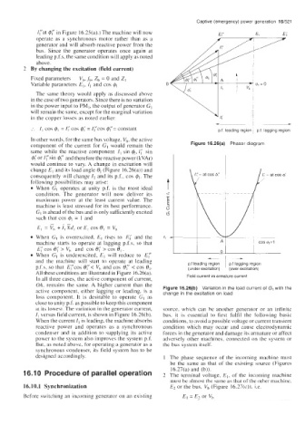
:. I, cos 4, = I; cos @; = I('cos @('= constant p f leading region 1 p f lagging region
In other words, for the same bus voltage, V,, the active
component of the current for GI would remain the Figure 16.26(a) Phasor diagram
same while the reactive component I, sin 4, I,' sin
4' or /('sin 4" and therefore the reactive power (kVAr)
would continue to vary. A change in excitation will
change E, and its load angle (Figure 16.26(a)) and
consequently will change I, and its p.f., cos @,. The
following Dossibihties mav arise:
When-dl operates at uhty p.f. is the most ideal
condition. The generator will now deliver its
maximum power at the least current value. The
machine is least stressed for its best performance.
GI is ahead of the bus and is only sufficiently excited
such that cos @I = 1 and
E, = v, + 7, gd, or E, cos 8, = V,
When GI is overexcited, E, rises to E; and the
machine starts to operate at lagging p.f.s, so that
E,' cos 8; > V,, and cos 8,' > cos 8,.
When GI is underexcited, El will reduce to E(' -
- I
and the machine will start to operate at leading p.f leading region I p.f lagging region
p.f.s, so that E('cos e('< V, and cos 8: < cos 81. (under excitation) (over excitation)
All these conditions are illustrated in Figure 16.26(a).
In all three cases, the active component of current, Field current vs armature current
OA, remains the same. A higher current than the
active component, either lagging or leading, is a Figure 16.26(b) Variation in the load current of G, with the
change in the excitation on load
loss component. It is desirable to operate GI as
close to unity p.f. as possible to keep this component
at its lowest. The variation in the generator current, source, which can be another generator or an infinite
I, versus field current, is shown in Figure 16.26(b). bus, it is essential to first fulfil the following basic
When the current II is leading, the machine absorbs conditions, to avoid a possible voltage or current transient
reactive power and operates as a synchronous condition which may occur and cause electrodynamic
condenser and in addition to supplying its active forces in the generator and damage its armature or affect
power to the system also improves the system p.f. adversely other machines, connected on the system or
But, as noted above, for operating a generator as a the bus system itself.
synchronous condenser, its field system has to be
designed accordingly. 1 The phase sequence of the incoming machine must
be the same as that of the existing source (Figures
16.27(a) and (b)).
16.1 0 Procedure of parallel operation 2 The terminal voltage, E,, of the incoming machine
must he almost the same as that of the other machine,
16.10.1 Synchronization E2 or the bus, V, (Figure 16.27(c)), i.e.
Before switching an incoming generator on an existing E, = E2 or V,