
Page 553 - Industrial Power Engineering and Applications Handbook
P. 553
Captive (emergency) power generation 16/527
I I I I
i
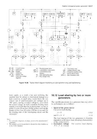
Ml-M4 - Circuit breaker 32 - Reverse power relay 2 - Time delay relay
GI-G3 - Generator LBR-A - Load balance relay active UNI - Voltage balance relay
PM,-PM, - Engine LBR-R - Load balance relay FNI - Frequency balance relay
GOV - Governor reactive SY1 - Synchronizing relay
51-54 - Selector Sw. 78 - Main decoupling relay SFG-3 - Bus frequency relay
AVR - Automatic voltage 27 - Bus voltage relay
regulator
Figure 16.36 Typical block diagram illustrating an auto-synchronizing and load-sharing
main supply, as a result a fast auto-reclosing, the 16.12 Load sharing by two or more
machine may be subject to mechanical damage or a generators
fault condition. A small delay would throw the two
sources out of synchronization and voltages up to
180" apart, causing a residual voltage Ec, up to twice The variable parameters in a generator that may affect
the system voltage. In such a situation the relay must its performance are as follows:
operate even faster than the reclosing time, as fast as
within 1 cycle (20 ms for a 50 Hz system) and trip the Speed of the prime mover
breaker in less than 10 cycles (200 ms) to account for For active load sharing,
the tripping time of the interrupting circuit and the f-N ( 1 ha)
interrupter.
and P- N. T ( 1.2)
The load sharing of the two generators is therefore
Note.\ dependent on the speed-load (drooping) characteristics
1 For schematic diagrams of relays, refer to the manufacturers' of the prime movers.
catalogues.
1 The numbers given in parentheses denote the relay numbers as Excitation voltage For reactive load sharing,
in the ANSI standard. P= \?.E.ICOS$