
Page 85 - Industrial Power Engineering and Applications Handbook
P. 85
3/66 Industrial Power Engineering and Applications Handbook
duration t2 a very light load P1 for a duration t, and at no perform the next operation it has gained enough
load for rest of one cycle. momentum and regained its consumed energy capable
For such load requirements, one may either choose a of performing the next operation without undue stress
comparatively larger motor to sustain the load and torque on the motor. This permissible speed variation may be as
requirements during shock loading or a smaller motor, low as 1-2% in steam engines and as high as 15-20%
depending upon the average equivalent loading Peq as for punches and shears, etc.
discussed earlier. When choosing a smaller motor it would
be advisable to absorb and smooth the shocks first to 3.9.2 Energy stored by the flywheel
contain the additional shock burden on the motor, as
well as on the main machine. This is made possible by
adding more moments of inertia to the drive by introducing (3.13)
a flywheel in the system, as shown in Figure 3.19. The
flywheel will now share a substantial jerk of the peak where
load, because it possesses a high inertia, on the one hand, F = energy stored by the flywheel in Joules
and is already in motion, on the other, before the load W = weight of the flywheel in kg
jerk is applied. The motor now has to share only a moderate V1 = velocity of the flywheel in m/s
jerk and a smaller motor can safely perform the required g = 9.81 m/s2
shock duty. During peak load, the stored kinetic energy
of the flywheel is utilized to perform the load requirement. After performing the duty, if the velocity of the flywheel
This energy is regained when the motor picks up after drops to V2 then the energy shared by the flywheel while
absorbing the shock load
performing the task. Motors for such applications can
be built with larger air gaps which may mean a low power
factor and a higher slip, but a higher capacity to sustain - W(V,' - v,' ) Joules
-
shocks. 2.g
From the peak load P2 and from the available h.p. of the
3.9.1 Size of flywheel motor Peq, we can determine the energy to be shared by
This is a mechanical subject, but is discussed briefly for the flywheel, i.e.
more clarity. The size of the flywheel, as well as the size
of the motor, will depend upon the speed variation that (3.14)
will be permissible for the type of duty being performed.
It should be such that by the time the machine must (T2 and Teq are in Joules)
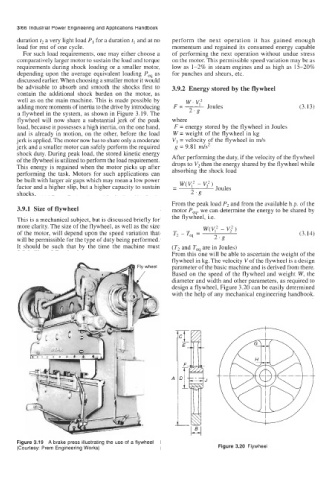
From this one will be able to ascertain the weight of the
flywheel in kg. The velocity V of the flywheel is a design
Fly wheel parameter of the basic machine and is derived from there.
/ Based on the speed of the flywheel and weight W, the
diameter and width and other parameters, as required to
design a flywheel, Figure 3.20 can be easily determined
with the help of any mechanical engineering handbook.
7
F-
A
Figure 3.19 A brake press illustrating the use of a flywheel
(Courtesy: Prem Engineering Works) Figure 3.20 Flywheel