Page 80 - Industrial Power Engineering and Applications Handbook
P. 80

Duties of  induction motors  3/61
                                                          0.2


                                                         0.18


                                                         0.16

                                                         0.14


                                                       -
                                                       t O.I2
                                                       8  0.1
                                                       E
                                                       (I)
                                                         0.08

                                                         0.06
                                              LL2.0
                                              @m
                                             - L1.5      0.04
                                              Om
                                             - BC,,  .2
                                              @m
                                                  .o
                                             ~Bc=l       0.02
                                              om
                                              %=0.75
                                              ern
                                                           0
               0   1'2    3   4      6  7                   0   1   2  3   4   5   6  7
                   150'7,
              ~
                  Y
             Only these portions
            of  curves are relevant
                                                                         Only these portions
                                                                        of curves are relevant
        (a) For   1.   s 200%                               I
                                                       (b) For   > 200%
                                                            4
                                                   ' I
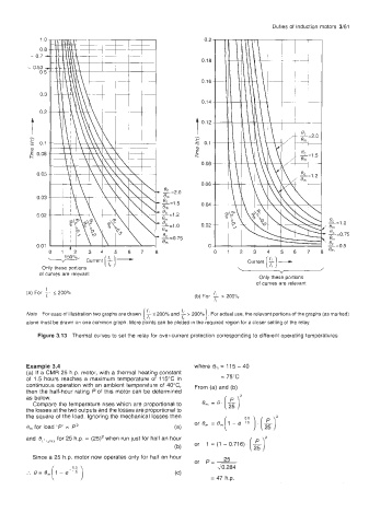
         Note  For ease of illustration two graphs are drawn  ($5  200% and  1,   > 200%  , For actual use, the relevant portions of the graphs (as marked)
        alone must be drawn on one common graph. More points can be plotted in the required region for a closer setting of the relay.
            Figure 3.13  Thermal curves to set the relay for over-current  protection corresponding to different operating temperatures


        Example 3.4                                    where  Om = 115 - 40
        (a) If a CMR 25 h.p. motor, with a thermal heating constant
        of  1.5 hours reaches  a  maximum temperature  of  115°C  in   = 75°C
        continuous  operation with an ambient  temperature  of 40°C,   From (a) and (b)
        then the half-hour  rating P of this  motor can be determined   om = 0. (3
        as below.
          Compare the temperature  rises which are proportional to
        the losses at the two outputs and the losses are proportional to
        the square of the load. Ignoring the mechanical  losses then   - e-% ) . (51'
         Om  for load 'P' = P'                    (a)   or om = e,[i
        and  @(,  ,ph,,  for 25 h.p. = (25)'  when run just for half an hour
                                                       or  1 = (1 - 0.716).
                                                  (b)
          Since a 25 h.p. motor now operates  only for  half an hour   25
                                                       or  P=-
                                                             210.284
                                                            = 47 h.p.
   75   76   77   78   79   80   81   82   83   84   85