
Page 75 - Industrial Power Engineering and Applications Handbook
P. 75
3/56 Industrial Power Engineering and Applications Handbook
I Example 3.1
If GD; = 0.16 kg m'
and GD: = 0.8 kg m' at motor speed
3.5 Heating and cooling
characteristic curves
The heating and cooling behaviour of an induction motor,
up to around twice the rated current, may be considered
as exponential, as a part of the heat generated is offset by
the heat sink (heat dissipation) through the windings.
But beyond 21, it should be considered adiabatic (linear),
as the heat generated is now quick and the winding
insulation may not be able to dissipate this heat equally
quickly, when it occurs for a short duration. Since a
"t Temperature rise motor would normally operate at around I, except during
abnormal operating conditions, the exponential heating
attained during and cooling characteristics are more relevant during a
one duty cycle normal run. They determine the performance of a motor,
particularly when it is required to perform intermittent
duties, and help determine safe loading, starts and brakings
etc. (See curves (a) and (b) of Figure 3.11). They also
Time - (B= 0) assist in providing a thermal replica protection to large
motors. With the help of these curves a motor protection
relay (Section 12.5) can be set to closely monitor the
thermal conditions prevailing within the machine, and
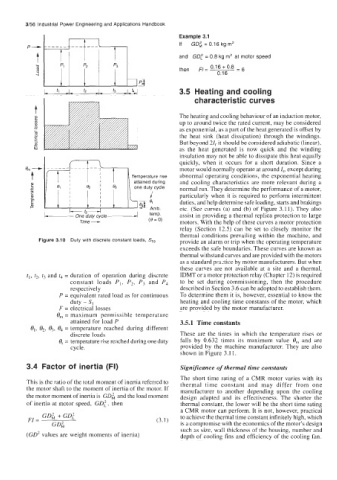
Figure 3.10 Duty with discrete constant loads, Sl0 provide an alarm or trip when the operating temperature
exceeds the safe boundaries. These curves are known as
thermal withstand curves and are provided with the motors
as a standard praztice by motor manufacturers. But when
these curves are not available at a site and a thermal,
t,, t,, tg and t4 = duration of operation during discrete IDMT or a motor protection relay (Chapter 12) is required
constant loads PI, P,, P3 and P4 to be set during commissioning, then the procedure
respectively described in Section 3.6 can be adopted to establish them.
P = equivalent rated load as for continuous To determine them it is, however, essential to know the
duty - Si heating and cooling time constants of the motor, which
F = electrical losses are provided by the motor manufacturer.
6, = maximum permissible temperature
attained for load P 3.5.1 Time constants
01, e,, e,, 6, = temperature reached during different
discrete loads These are the times in which the temperature rises or
6, = temperature rise reached during one duty falls by 0.632 times its maximum value e,,, and are
cycle. provided by the machine manufacturer. They are also
shown in Figure 3.1 1.
3.4 Factor of inertia (FI) Significance of thermal time constants
The short time rating of a CMR motor varies with its
This is the ratio of the total moment of inertia referred to thermal time constant and may differ from one
the motor shaft to the moment of inertia of the motor. If manufacturer to another depending upon the cooling
the motor moment of inertia is GD; and the load moment design adapted and its effectiveness. The shorter the
of inertia at motor speed, GD; , then thermal constant, the lower will be the short time rating
a CMR motor can perform. It is not, however, practical
GD; + GD; to achieve the thermal time constant infinitely high, which
FI = (3.1)
GD; is a compromise with the economics of the motor's design
such as size, wall thickness of the housing, number and
(GO2 values are weight moments of inertia) depth of cooling fins and efficiency of the cooling fan.