
Page 81 - Industrial Power Engineering and Applications Handbook
P. 81
3/62 industrial Power Engineering and Applications Handbook
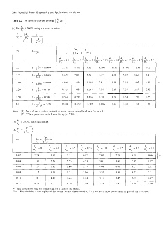
Table 3.2 In terms of current settings
I
(a) For -L 5 200'37, using the same equation
I,
1
t /T 1 --
et I?
O.O1 I 1 - - 0.0099 3.178 4.495
=
I.bl
0.05 I 1 - - 0.0476 XqG-
1
=
1.05
0.10 I 1 - - 0.095 1.026 I 1.451 *
1
=
1.105
0.20 I 1 - - 0.180 1.667 I 2.04 I 2.36 1 2.58 1 2.89 1 3.33
=
1.;2
0.50 I 1 - - 0.394 1.126 1 1.38 , 1.59 1.74 1.95 L
1
=
1.0 1 1 - 1 -- 0.632 0.398 1 0.562 0.889 I 1.089 1 1.26 1 1.38 I 1.54 1 1.78 I
1.65
2,718
Notes (1) For a closer overload protection, more curves should be drawn for f/r > 1
(2) *These points are not relevant for ll/lr < 200%.
I
(b) 1 200'37, using equation (b)
>
I,
lB,
11
I, 4K.t
].e. - =
0.10 1 .0 1.41 2.24 2.74 1.16 3.46 3.87 4.47
0.20 0.7 1 I .0 1 .58 1.94 2.24 2.45 2.74 3.16
**These conditions may not occur even on a fault in the motor.
Nore For obtaining a true replica of the motor thermal characteriatics, I* - I and 0 - t mure curves may be plotted for rlz < 0.02