
Page 888 - Industrial Power Engineering and Applications Handbook
P. 888
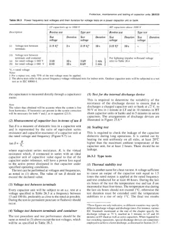
LT  capacitors up to 1000 V         HT  capacitors above IO00 V
       Description             Routine test       Type test        Routine test     Type test
                               Test      Duration   Test   Duration   Test   Duration  Test   Duration
                               voltage            voltage          voltage          voltage
       (i)  Voltage test between   2.15 V:   2s   2.15 V:   10 s   2.15 V:   10s    -      -
           terminals
       (ii)  Voltage test between
          terminals and container                                  For lightning impulse withstand voltage
       (a)  for rated voltage 5 660 V   3 kV   10 s   3 kV         refer to Table 26.4
       (b)  for rated voltage > 660  V   6 kV   10 s   6 kV   1  min
       "V, = rated voltage
       Notes
       1  For a repeat test, only 75% of the test voltage must be applied.
       2  The above tests refer to dry power frequency voltage withstand tests for indoor units. Outdoor capacitor units will be subjected to a wet
         test as in IEC 60060- 1.


       the capacitance is measured directly through a capacitbce   (5) Test for the internal discharge device
       meter.
                                                      This  is  required  to  determine  the  suitability  of  the
                                                      resistance  of  the  discharge  device  to  ensure that  it
       Note                                           discharges a charged capacitor unit or bank at fi V, to
       The values thus obtained will be accurate when the system is free
       from harmonics. If harmonics are present in the system correction   50 V or less in 1 minute in LT and in  10 minutes in HT
       will be necessary for both V andf, as in equation (23.5).   shunt capacitor units or banks and in 5 minutes in series
                                                      capacitors. The arrangements of  discharge devices  are
       (2) Measurement of capacitor loss in terms of tan 6   illustrated in Figure 25.8.*
       Tan 6 is a measure of dielectric loss in a capacitor unit   (6) Scaling test
       and  is  represented  by  the  ratio  of  equivalent  series
       resistance and capacitive reactance of a capacitor unit at   This  is required  to check the  leakage of  the capacitor
       the rated voltage and frequency (Figure 9.7) Le.   dielectric  during  long  operations.  It  is  carried  out  by
                                                      heating  the  unit  uniformly  on all  sides,  at  least  20°C
              R
       tan 6= -                                       higher  than  the  maximum  ambient temperature of  the
             xc                                       capacitor unit, for at least 2 hours. There should be no
       where  equivalent  series  resistance, R, is  the  virtual   leakage.
       resistance  which,  if  connected  in  series  with  an  ideal
       capacitor unit  of  capacitive  value  equal  to that  of  the   26.3.2 Type tests
       capacitor under reference, will have a power loss equal
       to the  active power  dissipated  in  that  capacitor  under   (I) Thermal stability test
       specified operating conditions.
        The test can be performed at voltages and frequencies,   This is another name for a heat run test. A voltage sufficient
       as noted  in  (1) above.  The value  of  tan  6 should  not   to  cause  an  output  of  the  capacitor  unit  equal  to  1.5
       exceed the declared value.                     times the rated output is applied at the rated frequency
                                                      and test conducted for at least 48 hours. During the last
       (3) Voltage test between terminals             six hours  of  the test the temperature rise and tan  6 are
                                                      measured at least four times. The temperature rise during
       Every capacitor unit will be subject to an a.c. test at a   the last six hours should not exceed 1"C, otherwise the
       voltage  specified in Table 26.3 at a frequency between   test  duration  must  be  extended  until  the  temperature
       15 and 100 Hz, preferably as close to the rated as possible.   stabilizes  to a rise  of  only  1°C. The final  test  results
       During the test no permanent puncture or flashover should
       occur.
                                                      *These figures are only indicative, as different countries may specify
                                                      different discharge voltages and discharge times. For instance, various
      (4) Voltage test between terminals and container   IEC  Standards mentioned at  the end  of  the chapter  specify the
                                                      discharge voltage as  75 V,  reached in  3  minutes in  LT  and  10
      The test procedure and test performance should be the   minutes in HT shunt as well as series capacitors. When required for
      same as noted in (3) above except the test voltages, which   fast switching operations, special discharge devices are sometimes
      will be as specified in Table 26.3.             employed to achieve a faster discharge, as discussed in Section 23.17.