
Page 885 - Industrial Power Engineering and Applications Handbook
P. 885
26/836 Industrial Power Engineering and Applications Handbook
For more ground
fault schemes
refer to Ch. 21
Surge VT
arresters
I 'P 'p
Line side
series tf --
reactor Capacitors' discharge secondary winding
V-(open delta)
tertiary winding
I I r
~~
I11
w To monitor discharge To NDR
conditions of the
Ungrounded capacitor banks
capacitor banks
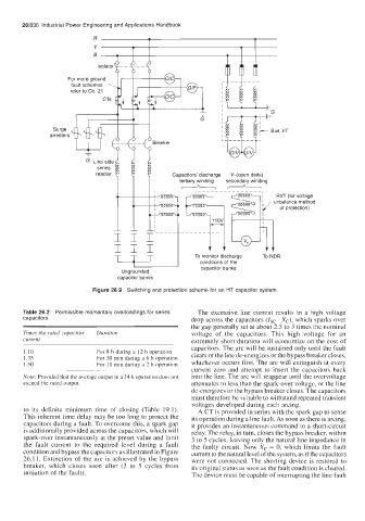
Figure 26.9 Switching and protection scheme for an HT capacitor system
Table 26.2 Permissible momentary overloadings for series The excessive line current results in a high voltage
capacitors drop across the capacitors (Isc . Xc), which sparks over
the gap generally set at about 2.5 to 3 times the nominal
Times the rated capacitor Duration voltage of the capacitors. This high voltage for an
current extremely short duration will economize on the cost of
capacitors. The arc will be sustained only until the fault
110 For 8 h during d 12 h operation
135 For 30 min during a 6 h operation clears or the line de-energizes or the bypass breaker closes,
150 For 10 min during a 2 h operation whichever occurs first. The arc will extinguish at every
current zero and attempt to insert the capacitors back
~~ ~
Note Provided that the average output in a 24 h operation does not into the line. The arc will reappear until the overvoltage
exceed the rated output attenuates to less than the spark-over voltage, or the line
de-energizes or the bypass breaker closes. The capacitors
must therefore be suitable to withstand repeated transient
voltages developed during each arcing.
to its definite minimum time of closing (Table 19.1). A CT is provided in series with the spark gap to sense
This inherent time delay may be too long to protect the its operation during a line fault. As soon as there is arcing,
capacitors during a fault. To overcome this, a spark gap it provides an instantaneous command to a short-circuit
is additionally provided across the capacitors, which will relay. The relay, in turn, closes the bypass breaker, within
spark-over instantaneously at the preset value and limit 3 to 5 cycles, leaving only the natural line impedance in
the fault current to the required level during a fault the faulty circuit. Now X, = 0, which limits the fault
condition and bypass the capacitors as illustrated in Figure current to the natural level of the system, as if the capacitors
26.11. Extinction of the arc is achieved by the bypass were not connected. The shorting device is restored to
breaker, which closes soon after (3 to 5 cycles from its original status as soon as the fault condition is cleared.
initiation of the fault). The device must be capable of interrupting the line fault