Page 889 - Industrial Power Engineering and Applications Handbook
P. 889
26/840  Industrial Power Engineering and Applications Handbook
       compared to  the measurement taken  at the  start of  the   For LT  units: Three impulses  should be  applied of
       test should not vary by more than the following:   positive polarity followed by three of negative between
                                                        the terminals joined together and the container.
         For capacitance value                          For HT units: Fifteen impulses should be applied of
         For LT units: 2% of its capacitance value      positive polarity followed by fifteen of negative between
         For HT units: The two test values should be corrected   the bushings joined together and the container.
         to the  same reference  of  dielectric  temperature,  say,
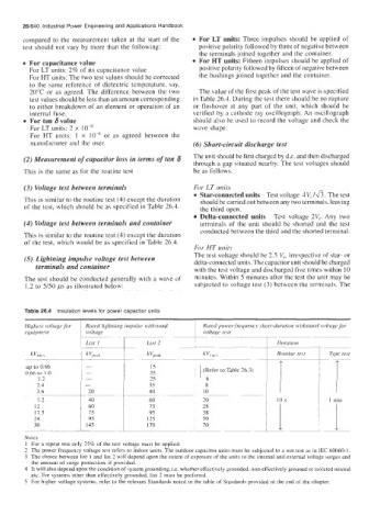
         20°C  or  as  agreed. The difference  between  the  two   The value of the first peak of the test wave is specified
         test values should be less than an amount corresponding   in Table 26.4. During the test there should be no rupture
         to either breakdown of an element or operation of an   or  flashover  at  any  part  of  the  unit,  which  should  be
         internal fuqe.                               verified by  a cathode ray  oscillograph. An oscillograph
         For tan 6value                               should also be used to record the voltage and check the
         For LT units: 2 X  IO4                       wave shape.
         For  HT  units:  1  x  lo4  or  as  agreed  between  the
         manufacturer and the user.                   (6) Short-circuit discharge test

        (2) Measurement of capacitor loss in terms of tan 6   The unit should be first charged by d.c. and then discharged
                                                      through a gap situated nearby. The test voltages should
        This is the same as for the routine test      be as follows.

        (3) Voltage test between terminals            For LT units
                                                        Star-connected units  Test voltage  4 V, /a. The test
        This is similar to the routine test (4) except the duration   should be carried out between any two terminals, leaving
        of the test, which should be as specified in Table 26.4.   the third  open.
                                                        Delta-connected units   Test  voltage  2V,.  Any  two
        (4) Voltage test between terminals and container   terminals  of  the  unit  should  be shorted  and the test
                                                        conducted between the third and the shorted terminal.
        This is similar to the routine test (4) except the duration
        of the test,  which would be as specified in Table 26.4.
                                                       For HT units
        (5) Lightning impulse voltage test between    The test voltage should be 2.5 V,, irrespective of star- or
                                                      delta-connected units. The capacitor unit should be charged
           terminals and container                     with the test voltage and discharged five times within  10
        The test should be conducted generally with a wave  of   minutes. Within  5 minutes after the test the unit may be
        1.2 to 5/50 ps as illustrated below:           subjected to voltage test (3) between the terminals. The


        Highest vulruge for   Rated  lightning impulse withstund   Rated power-frequency short-durcition  withstand volttrge for

                                                                             Durution
                                                                             Routine  test   1   Type test
        up to 0.66
        0.66 to  1.0
            1.2
            2.4
            3.6
            7.2           40                                                  10 s
           12             60
           11.5           75                                               ~. 1
           24             9s
           36            145

        Notes
        1  For a repeat test only 7S% of  the test  voltage must be applied.
        2  The power frequency voltage test refers to indoor units. The outdoor capacitor units must be subjected to a wet test as in IEC 60060-1.
        3  The choice between list  I  and list 2 will depend upon the extent of exposure of the units to the internal and external voltage surges and
          the amount of surge protection, if provided.
        4  It will also depend upon the condition of system grounding, i.e. whether effectively grounded. non-effectively grouned or isolated neutral
          etc. For systems other than effectively grounded, list 2 must be preferred.
        S For higher voltage systems, refer to the relevant Standards noted in the table of  Standards provided at the end of  the chapter.

