
Page 984 - Industrial Power Engineering and Applications Handbook
P. 984
An isolated phase bus system 31/929
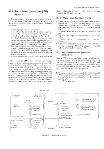
31.1 An isolated phase bus (IPB) plant is illustrated in Figure 31.2(a) and (b). It may
system comprise the following sections.
31.1.1 Main run and auxiliary feed lines
In this construction the conductors of each phase are
housed in a separate non-magnetic metallic enclosure to 1 From generator phase terminals to the lower voltage
isolate them completely from each other with the following side of the GT. This section may partly be indoors,
advantages: connecting the generator inside the turbine room and
partly outdoors, connecting the GT in the transformer
I It eliminates phase-to-phase faults. yard.
2 It eliminates the proximity effect (extra forces and 2 A generator neutral bus to form the generdtor star
heating) by providing a magnetic shielding to the point.
\upporting and metallic structures in the vicinity. 3 Tap-offs with tee joints from the main run to the two
3 It reduces the proximity effects between the main UATs.
current-carrying conductors of the adjacent phases to 4 Sometimes from UAT secondaries to the unit HT
almost zero due to magnetic shielding, on the one switchgears.
hand. and large centre spacing, on the other. 5 If the GT is made of three, single-phase transformers,
4 It provides complete protection for operating personnel an interconnecting IPB will be required to form the
t'roin high touch or step voltages (for details on contact delta as illustrated in Figure 3 I .?(b).
voltages. see Section 22.9) across the enclosure and
the metallic structures caused by parasitic (electro- 31.1.2 Instrumentation and protection
magnetic) currents. connections
5 The bu\ system is are easy to handle, bend and install.
Since an IPB forms an important integral part ofa power-
This is used for HT systems of very large ratings. generating station, with it are associated a number of
Since it is a more expensive arrangement it is normally metering and protective devices such as CTs, VTs and
preferred only for crirical installations such as a power generator grounding system. Below we identifiy inter-
generating station. where it has to carry large to very connections that may be required to connect these CTs
large currents due to high ratings of the generating units. and VTs while installing an IPB system.
In a thermal power plant it is used between the generating
unit (G) and the generator transformer (GT) and the unit I Removable links for easy mounting and maintenance
auxiliary transformers (UATs) as well as sometimes of CTs for metering and protection. typically as follows.
between the UAT and the unit HT switchgear as illustrated For each phase in the main lines between the yenerator
in Figure 13.2 1 (redrawn in Figure 3 1.1 for more clarity). and the GT,
A typical layout of such a bus system in a thermal power 1 CT for metering
To switch yard
.
Transformer Generator
transformer
- Three phase two wind
Tap-off
connection 1 ~ Tee joints Tap-off ing transformer (UAT)
Outdoor
installation - Three phase two wind-
ing transformer with ON
load tap changer (GT)
Unit bus duct Circuit breaker
chamber
J HT breaker
Indoor H T breaker
installation ( 33 kV/ll kV/
I 66kV
Figure 31.1 Application of an IPB