
Page 989 - Industrial Power Engineering and Applications Handbook
P. 989
31/934 Industrial Power Engineering and Applications Handbook
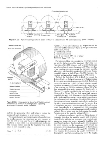
Fibre glass insulating pad
Figure 31.5(a) Typical insulating practice to isolate enclosure of a discontinuous IPB system (Courtesy: Best & Crompton)
Main bus conductor Figures 31.7 and 31.8 illustrate the disposition of the
conductor and the enclosure fields in the space and their
nullification, where
I, = conductor current
I, = enclosure current
I, and I, are almost 180" out of phase.
therefore, (I, - I,)
For better shielding it is essential that bonding is carried
out at the farthest possible locations where the con-
figuration of the IPB changes such as at the bends and
tap-offs or where it passes through a wall. Where bonding
is not possible, the supports and the enclosure must be
adequately reinforced to sustain electrodynamic forces,
especially during a fault. Figure 3 1.2(b) illustrates the
shorting and grounding locations of an IPB system.
To limit the fault level, if it is likely to exceed the
designed limits, or the breaking capacity of the interrupting
device, or the associatedequipment and to limit the induced
AI. shorting band circulating currents in the enclosure during normal
operation, to contain enclosure losses in very large ratings
Support insulator
of bus systems, say, 25 OOOA and above (above 500 MW),
then unsaturable type series reactors (for details refer to
Chapter 27) may be provided in the enclosure circuit, as
insulating pad illustrated in Figure 31.8 to limit such high currents
Galvanized steel especially during a fault. The reactors should not saturate
support structure under fault conditions, as they are provided to supplement
the enclosure circuit impedance to limit the high currents
through the enclosure, especially during faults, and reduce
Figure 31.5(b) Cross-sectional view of an IPB with insulated the forces between the main conductors. For a better flow
(discontinuous) enclosure illustrating busbar-supporting
arrangement (Courtesy: Best & Crompton) of circulating currents, it is also grounded only at one
point. Accordingly, it is supported on non-conducting
supports to keep the ground path continuous and completely
isolated. The enclosure must also be insulated electrically
nullifies the proximity effect and helps to reduce the from the rest of the plant by rubber bellows.
heating of such structures to a very great extent. A continuous enclosure provides a high degree of
The electrodynamic and electromagnetic forces between magnetic shielding for metallic objects and structures
the conductors and the structures are also reduced to located in the vicinity and generates only nominal eddy
only 10-15% or even less. These two advantages are not current or hysteresis losses. Magnetic shielding also
available to this extent in a non-continuous enclosure. significantly reduces the electrodynamic stresses caused
The induced current causing the magnetic field in the by short-circuits on the structures and between the
space is now reduced to only, enclosures of the other phases. For details on the thickness
and size of enclosure to provide magnetic shielding up
(31.1) to a required level, refer to the sample calculations in
Example 3 1.1 and further reading at the end of this chapter.