
Page 992 - Industrial Power Engineering and Applications Handbook
P. 992
An isolated phase bus system 31/937
I- Generator
Indoor I Outdoor
/ *-e
k
k
Power house wall
-
i *, \
Hot air -
-. . - Tap-off t t7
1- .-
1-
to U.A.T
outlet
Generator
Unit aux. transformer
transformer
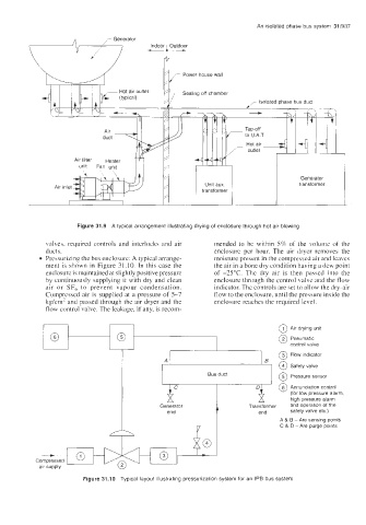
Figure 31.9 A typical arrangement illustrating drying of enclosure through hot air blowing
valves. required controls and interlocks and air mended to be within 5% of the volume of the
ducts. enclosure per hour. The air dryer removes the
Pressurizing the bus enclosure: A typical arrange- moisture present in the compressed air and leaves
ment is shown in Figure 31.10. In this case the the air in a bone dry condition having a dew point
enclosure is maintained at slightly positive pressure of -25°C. The dry air is then passed into the
by continuously supplying it with dry and clean enclosure through the control valve and the flow
air or SF, to prevent vapour condensation. indicator. The controls are set to allow the dry-air
Compressed air is supplied at a pressure of 5-7 flow to the enclosure, until the pressure inside the
kg/cm' and passed through the air dryer and the enclosure reaches the required level.
flow control valve. The leakage, if any, is recom-
2 Pneumatic
0 control valve
@ Safety valve
I Bus duct I 0 Pressure sensor
(for low pressure alarm,
high pressure alarm
Generator Transformer and operation of the
safety valve etc.)
A & B -Are sensing points
V I C 8. D - Are purge points
(3
- -
-
-
Compressed
air supply
Figure 31.10 Typical layout illustrating pressurization system for an IPB bus system