
Page 995 - Industrial Power Engineering and Applications Handbook
P. 995
31/940 Industrial Power Engineering and Applications Handbook
the conductor and the enclosure rather than between two
phases due to an almost negligible or only moderate
magnetic field in the space (Figures 3 1.7 and 3 1.8). The
emphasis is now more on the losses in the enclosure and
t the metallic structures outside the enclosure and their
consequent heating, rather than the derating of the current-
5 carrying conductors.
To arrive at the most appropriate and economical design
2 of the enclosure is a complex subject and requires detailed
D
- study. For brevity, in our present attempt, we have derived
P
inferences from the established work in this field by
22
co engineers and authors (see the further reading) and have
underlined briefly the basic approach to design such a
,zs;, 1 system. For smaller ratings, up to 3200A, the discussions
in Chapter 28 will generally suffice to design a good bus
Minimum - system. There we have assumed the content of proximity
losses on the conductors and exercised care while selecting the
size and material of the enclosure, spacings between the
Enclosure thickness 't' - two adjacent phases etc. In an IPB system, however,
0 enclosure and the busbars and between the busbars of
may cause excessive parasitic currents within the enclosure
t, = Thickness of enclosure for minimum cost of IPB when the space occupied by the electric field is large
system (Figure 31.13) and in the metallic structures in close proximity outside
the enclosure and excessive heating in both. The
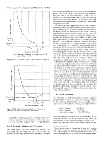
Figure 31.12 Variation in losses with thickness of enclosure assumptions made earlier may not suffice for its effect
on the enclosure, supports and the structures in the vicinity.
To provide magnetic shielding within the enclosure
will require the enclosure to be made of non-magnetic
material at the first instance to eliminate magnetic losses
and a cross-section sufficient to carry a near full load
t current on the other. It is also essential to allow a nil or
only a moderate field in the space outside the enclosure
E to limit the parasitic currents in the supporting and other
2 metallic structures so that they do not require any special
$
m treatment or insulation and protect the operating personnel
9 from excessive touch or step voltages. The main emphasis
%.
to design such a system is therefore to optimize the
1
v) thickness of the enclosure and its overall size to obtain
8
.-. the required magnetic shielding and a temperature rise
SI!
co within desirable limits.
31.4.4 Solar radiation
The part of the bus enclosure installed outdoors is exposed
Cost at $4
Minimun to solar radiation which is a cause of additional heat gain
cost ~ by the enclosure. ANSI C-37.24 has provided a basis to
determine its effect in terms of heat generated as follows:
Enclosure thickness 'f' --C
during winter - 670 W/m2
Figure 31.13 Optimization curve between thickness of during summer - 990 W/m2
enclosure and the total cost of the IPB system
for tropical areas* - 1 100-1 200 W/m2
By simulating these effects in a test laboratory it has
acceptable. Therefore, to choose a thinner enclosure is been established that solar radiation may raise the
common practice to economize on the total cost, temperature of the external surfaces by up to 15"C,
allowing part of the magnetic field to occupy the space. depending upon the colour and the condition of the surface.
31.4.3 Proximity effect in an IPB system
*Tropics are the regions of the earth that lie about 2570 km north
The three phases are now completely isolated and and 2570 km south and parallel to the equator (Figure 31.14).
adequately spaced. They are thus hardly under any These regions signify the areas that generally have a warm to hot
influence of proximity. The forces are now greater between climate throughout the year, as the sun reaches its greatest altitude.