
Page 403 - Industrial Wastewater Treatment, Recycling and Reuse
P. 403
An Introduction to Biological Treatment and Membrane Filtration 375
Influent Aeration tank Effluent
Clarifier
Air
Recycling pump
ASP Schematic
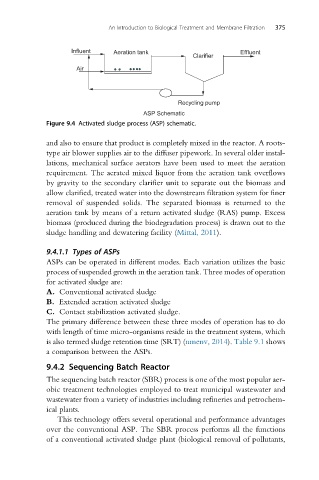
Figure 9.4 Activated sludge process (ASP) schematic.
and also to ensure that product is completely mixed in the reactor. A roots-
type air blower supplies air to the diffuser pipework. In several older instal-
lations, mechanical surface aerators have been used to meet the aeration
requirement. The aerated mixed liquor from the aeration tank overflows
by gravity to the secondary clarifier unit to separate out the biomass and
allow clarified, treated water into the downstream filtration system for finer
removal of suspended solids. The separated biomass is returned to the
aeration tank by means of a return activated sludge (RAS) pump. Excess
biomass (produced during the biodegradation process) is drawn out to the
sludge handling and dewatering facility (Mittal, 2011).
9.4.1.1 Types of ASPs
ASPs can be operated in different modes. Each variation utilizes the basic
process of suspended growth in the aeration tank. Three modes of operation
for activated sludge are:
A. Conventional activated sludge
B. Extended aeration activated sludge
C. Contact stabilization activated sludge.
The primary difference between these three modes of operation has to do
with length of time micro-organisms reside in the treatment system, which
is also termed sludge retention time (SRT) (nmenv, 2014). Table 9.1 shows
a comparison between the ASPs.
9.4.2 Sequencing Batch Reactor
The sequencing batch reactor (SBR) process is one of the most popular aer-
obic treatment technologies employed to treat municipal wastewater and
wastewater from a variety of industries including refineries and petrochem-
ical plants.
This technology offers several operational and performance advantages
over the conventional ASP. The SBR process performs all the functions
of a conventional activated sludge plant (biological removal of pollutants,