
Page 408 - Industrial Wastewater Treatment, Recycling and Reuse
P. 408
380 Industrial Wastewater Treatment, Recycling, and Reuse
used was 0.4 mm, which is microfiltration size, but once a biofilm layer was
formed over this surface, it worked in the UF range and produced filtrate with
good turbidity ( Judd, 2011). The PES-based (Polyethersulfone) flat mem-
brane over PP (Polypropylene) support was reportedly used in sewage appli-
cations subsequently at a 150 kDa pore size, which falls in the UF range.
Generally, air is used for removal of sludge over the membrane surface,
keeping the membranes fixed. In one instance, a moving membrane module
has also been developed to reduce the sludge adhering to the membrane sur-
face (Judd, 2011). There was a lot of development in the 1990s when com-
mercial applications were tried. Many players have participated in the
development and improvement of membrane performance and also have
improved processes to suit their particular products.
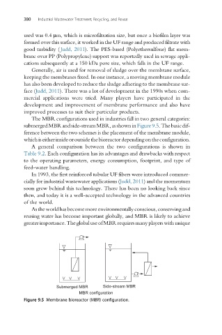
The MBR configurations used in industries fall in two general categories:
submergedMBRandside-stream MBR,asshowninFigure9.5.Thebasicdif-
ference between the two schemes is the placement of the membrane module,
whichiseitherinsideoroutsidethebioreactordependingontheconfiguration.
A general comparison between the two configurations is shown in
Table 9.2. Each configuration has its advantages and drawbacks with respect
to the operating parameters, energy consumption, footprint, and type of
feed-water handling.
In 1993, the first reinforced tubular UF fibers were introduced commer-
cially for industrial wastewater applications (Judd, 2011) and the momentum
soon grew behind this technology. There has been no looking back since
then, and today it is a well-accepted technology in the advanced countries
of the world.
Asthe world has become more environmentally conscious, conservingand
reusing water has become important globally, and MBR is likely to achieve
greaterimportance.TheglobaluseofMBRrequiresmanyplayerswithunique
Submerged MBR Side-stream MBR
MBR configuration
Figure 9.5 Membrane bioreactor (MBR) configuration.