
Page 411 - Industrial Wastewater Treatment, Recycling and Reuse
P. 411
An Introduction to Biological Treatment and Membrane Filtration 383
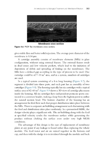
Figure 9.6 PVDF flat membrane cross section.
gives stable flux and better solid rejection. The average pore diameter of the
membrane is 0.04 mm.
A cartridge assembly consists of membrane elements (MEs) in plate
configuration, without using external frames. The external frames result
in dead zones and low velocity pockets, which lead to the initiation of
deposition of debris and spreading of fouling on the membranes. The
MEs have a defined gap according to the type of process to be used. One
2
cartridge could be of 7–10 m area, and in a system, numbers of cartridges
are used.
In a typical system consisting of a 4 m long housing (Figure 9.7), the
segment is divided into three parts, and each part has an assembly of two
cartridges (Figure 9.8). The housing typically has six cartridges with a typical
2
surface area of 42–60 m . Figure 9.9 shows a 3D view of cartridge placement
inside the housing. All six cartridges have independent permeate ports con-
nected in a common header, making a loop from the highest point to utilize
the natural suction head. The bottom chamber of the housing has an
arrangement for feed flow such that proper distribution takes place between
the MEs. There is a separate air bubbling arrangement such that mixing with
the feed and distribution takes place uniformly. In a pressurized MBR, the
design velocity plays a significant role. The air bubbling along with the feed
at specified velocity scrubs the membrane surface while generating the
product without choking the surface even under very high MLSS
conditions.
The advantage of this design is the ease of replacement of membrane
plates at any point if any leakage is found rather than replacing the whole
module. The feed water and air are mixed together in the bottom end
cap, and then with the sludge it is recirculated through the module and back