
Page 210 - Innovations in Intelligent Machines
P. 210
Evolutionary Design of a Control Architecture for Soccer-Playing Robots 203
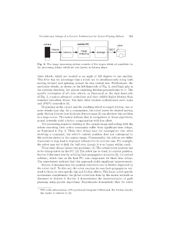
camera control PC
robot
firewire image DECT
memory strategie
analysing
Fig. 3. The image processing system consists of five stages which all contribute to
the processing delays, which are also known as latency times
three wheels, which are located at an angle of 120 degrees to one another.
This drive has the advantage that a robot can be simultaneously doing both
moving forward and spinning around its own central axis. Furthermore, the
particular wheels, as shown on the left-hand-side of Fig. 2, yield high grip in
the rotation direction, but almost-vanishing friction perpendicular to it. The
specific orientation of all three wheels, as illustrated on the right-hand-side
of Fig. 2, requires advanced controllers and they exhibit higher friction than
standard two-wheel drives. The later drive requires sophisticated servo loops
1
and (PID ) controllers [8].
Depending on the carpet and the resulting wheel-to-carpet friction, one or
more wheels may slip. As a consequence, the robot leaves its desired moving
path. Section 2 shows how Kohonen feature maps [4] can alleviate this problem
to a large extent. The results indicate that in comparison to linear algorithms,
neural networks yield a better compensation with less effort.
The processing sequence starting at the camera image and ending with the
robots executing their action commands suffer from significant time delays,
as illustrated in Fig. 3. These time delays have the consequence that when
receiving a command, the robot’s current position does not correspond to
the position shown in the camera image. Consequently, the actions are either
inaccurate or may lead to improper behavior in the extreme case. For example,
the robot may try to kick the ball even though it is no longer within reach.
These time delays induce two problems: (1) The actual robot position has
to be extrapolated on the PC. (2) The robot has to track its current position.
Section 3 discusses how by utilizing back-propagation networks [4], the control
software, which runs on the host PC, can compensate for those time delays.
The experiments indicate that this approach yields significant improvements.
Section 4 discusses how the position correction can be further improved by
the robot itself. To this end, the robot employs its own back-propagation net-
work to learn its own specific slip and friction effects. This local, robot specific
mechanism complements the global correction done by the neural network as
discussed in Section 3. Section 5 demonstrates the implementation of path
planning using genetic algorithms. Experiments demonstrate that the robot
1
PID is the abbreviation of Proportional-Integrate-Differential. For further details,
the reader is referred to [8]