
Page 214 - Innovations in Intelligent Machines
P. 214
Evolutionary Design of a Control Architecture for Soccer-Playing Robots 207
Kohonen Map × × + + PID
ϕ × + PID
PID
v Motors / Wheels
y
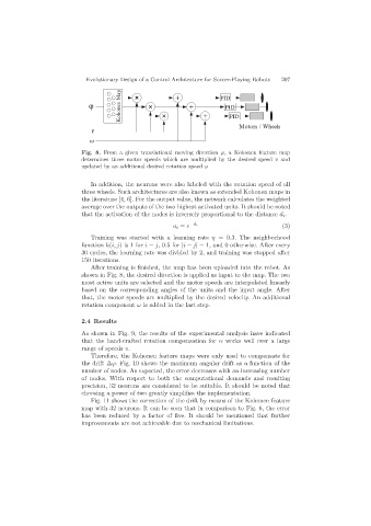
Fig. 8. From a given translational moving direction ϕ, a Kohonen feature map
determines three motor speeds which are multiplied by the desired speed v and
updated by an additional desired rotation speed ω
In addition, the neurons were also labeled with the rotation speed of all
three wheels. Such architectures are also known as extended Kohonen maps in
the literature [4, 6]. For the output value, the network calculates the weighted
average over the outputs of the two highest activated units. It should be noted
that the activation of the nodes is inversely proportional to the distance d i .
a i = e −d i (3)
Training was started with a learning rate η =0.3. The neighborhood
function h(i, j)is1for i = j, 0.5 for |i − j| = 1, and 0 otherwise. After every
30 cycles, the learning rate was divided by 2, and training was stopped after
150 iterations.
After training is finished, the map has been uploaded into the robot. As
shown in Fig. 8, the desired direction is applied as input to the map. The two
most active units are selected and the motor speeds are interpolated linearly
based on the corresponding angles of the units and the input angle. After
that, the motor speeds are multiplied by the desired velocity. An additional
rotation component ω is added in the last step.
2.4 Results
As shown in Fig. 9, the results of the experimental analysis have indicated
that the hand-crafted rotation compensation for α works well over a large
range of speeds v.
Therefore, the Kohonen feature maps were only used to compensate for
the drift ∆ϕ. Fig. 10 shows the maximum angular drift as a function of the
number of nodes. As expected, the error decreases with an increasing number
of nodes. With respect to both the computational demands and resulting
precision, 32 neurons are considered to be suitable. It should be noted that
choosing a power of two greatly simplifies the implementation.
Fig. 11 shows the correction of the drift by means of the Kohonen feature
map with 32 neurons. It can be seen that in comparison to Fig. 6, the error
has been reduced by a factor of five. It should be mentioned that further
improvements are not achievable due to mechanical limitations.