
Page 217 - Innovations in Intelligent Machines
P. 217
210 S. Pr¨uter et al.
Data in
servo loop
Real robot
position
Robot Robot reach Servo loop
Robot stay Robot stops
accelerate position send stop
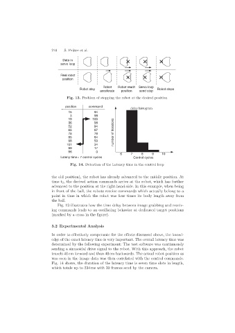
Fig. 13. Problem of stopping the robot at the desired position
position command
delay histogram
15 94
3 98
19 100
36 98
52 94
65 87
78 76 number of iterations
95 64
98 50
101 34
99 17
96 0
6 7 8 9 10
Lateny time= 7 control cycles Control cycles
Fig. 14. Detection of the Latency time in the control loop
the old position), the robot has already advanced to the middle position. At
time t 2 , the derived action commands arrive at the robot, which has further
advanced to the position at the right-hand-side. In this example, when being
in front of the ball, the robots receive commands which actually belong to a
point in time in which the robot was four times its body length away from
the ball.
Fig. 13 illustrates how the time delay between image grabbing and receiv-
ing commands leads to an oscillating behavior at dedicated target positions
(marked by a cross in the figure).
3.2 Experimental Analysis
In order to effectively compensate for the effects discussed above, the knowl-
edge of the exact latency time is very important. The overall latency time was
determined by the following experiment: The test software was continuously
sending a sinusoidal drive signal to the robot. With this approach, the robot
travels 40 cm forward and than 40 cm backwards. The actual robot position as
was seen in the image data was then correlated with the control commands.
Fig. 14 shows, the duration of the latency time is seven time slots in length,
which totals up to 234 ms with 30 frames send by the camera.