
Page 216 - Innovations in Intelligent Machines
P. 216
Evolutionary Design of a Control Architecture for Soccer-Playing Robots 209
3 Improved Position Prediction
As has been outlined in the introduction, the latency caused by the image-
processing-and-action-generation loop leads to non-matching robot positions.
As a measurable effect, the robot starts oscillating, turning around the tar-
get position, missing the ball, etc. This section utilizes a three-layer back-
propagation network to extrapolate the robot’s true position from the camera
images.
3.1 Latency Time
RoboCup robots are real-world vehicles rather than simulated objects. There-
fore, all algorithms have to account for physical effects, such as inertia and
delays, and have to meet real-time constraints. Because of the real-time con-
straints, exact algorithms would usually require too much a calculation time.
Therefore, the designer has to find a good compromise between computational
demands and the precision of the results. In other words, fast algorithms with
just a sufficient precision are chosen.
As mentioned in the introduction, latency is caused by various components
which include the camera’s image grabber, the image compression algorithm,
the serial transmission over the wire, the image processing software, and the
final transmission of the commands to the robots by means of the DECT mod-
ules. Even though the system uses the compressed YUV411 image format [7],
the image processing software, and the DECT modules are the most signifi-
cant parts with a total time delay of about 200 ms. For the top-level control
software, which is responsible for the coordination of all team members, all
time delays appear as a constant-time lag element. The consequences of the
latency problem are further illustrated in Fig. 12 and Fig. 13.
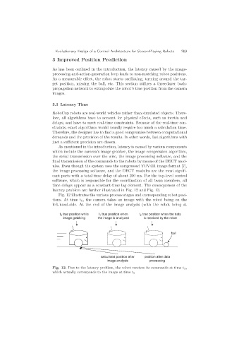
Fig. 12 illustrates the various process stages and corresponding robot posi-
tions. At time t 0 , the camera takes an image with the robot being on the
left-hand-side. At the end of the image analysis (with the robot being at
t true position while t true position when t true position when the data
2
1
0
image grabbing the image is analyzed is received by the robot
ball
calculated position after position after data
image analysis processing
Fig. 12. Due to the latency problem, the robot receives its commands at time t 2,
which actually corresponds to the image at time t 0