
Page 212 - Innovations in Intelligent Machines
P. 212
Evolutionary Design of a Control Architecture for Soccer-Playing Robots 205
2.2 Experimental Analysis
The various effects of slip and friction are experimentally measured in two
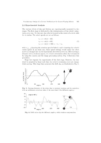
stages. The first stage is dedicated to the determination of the robot’s orien-
tation error ∆α. To this end, the robot is located in the center of a circle with
1m in radius. The wheel speeds are set as follows:
r 1 = v · sin(π − 60).
r 2 = v · sin(π + 60). (1)
r 3 = v · sin(π + 180) = −r 1 − r 2 .
with r i=1...3 denoting the rotation speed of wheel i and v denoting the robot’s
center speed. In an ideal case, these speed settings would make the robot
move in a straight line. In the experiment, the robot moves 1 m. After moving a
distance with a moderate speed, the robot’s orientation offset ∆α is measured
by using the camera and the image processing system. Fig. 5 illustrates this
procedure.
Stage two repeats the experiments of the first stage. However, the rear
wheel is adjusted by hand such that the robot’s orientation does not change
while moving. This stage then measures the drift ∆ϕ, as illustrated in Fig. 6.
5
4
3 2
correction value −1 1 0
−2
−3
−4
−5
−6 0 90 180 270 360
angle j
Fig. 5. Turning behavior of the robot due to internal rotation and its correction
with an additional correction value of the rear wheel 1 for different angles ϕ
15
angular drift j
10
5 j
0 j'
−5
−10 1m
90 180 270 360
angle j
Fig. 6. Drift values ∆ϕ for different angels ϕ with rotation compensation