
Page 221 - Innovations in Intelligent Machines
P. 221
214 S. Pr¨uter et al.
wireless
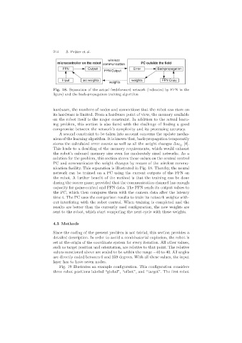
microcontroller on the robot communication PC outside the field
FFN Output Error Backpropagation
FFN Output
Input set weights weights FFN Copy
weights
Fig. 18. Separation of the actual feed-forward network (indicated by FFN in the
figure) and the back-propagation training algorithm
hardware, the numbers of nodes and connections that the robot can store on
its hardware is limited. From a hardware point of view, the memory available
on the robot itself is the major constraint. In addition to the actual learn-
ing problem, this section is also faced with the challenge of finding a good
compromise between the network’s complexity and its processing accuracy.
A second constraint to be taken into account concerns the update mecha-
nism of the learning algorithm. It is known that, back-propagation temporarily
stores the calculated error counts as well as all the weight changes ∆w ij [4].
This leads to a doubling of the memory requirements, which would exhaust
the robot’s onboard memory size even for moderately sized networks. As a
solution for the problem, this section stores those values on the central control
PC and communicates the weight changes by means of the wireless commu-
nication facility. This separation is illustrated in Fig. 18. Thereby, the neural
network can be trained on a PC using the current outputs of the FFN on
the robot. A further benefit of the method is that the training can be done
during the soccer game, provided that the communication channel has enough
capacity for game-control and FFN data. The FFN sends its output values to
the PC, which then compares them with the camera data after the latency
time t. The PC uses the comparison results to train its network weights with-
out interfering with the robot control. When training is completed and the
results are better than the currently used configuration, the new weights are
sent to the robot, which start computing the next cycle with these weights.
4.3 Methods
Since the coding of the present problem is not trivial, this section provides a
detailed description. In order to avoid a combinatorial explosion, the robot is
set at the origin of the coordinate system for every iteration. All other values,
such as target position and orientation, are relative to that point. The relative
values mentioned above are scaled to be within the range −40 to 40. All angles
are directly coded between 0 and 359 degrees. With all these values, the input
layer has to have seven nodes.
Fig. 19 illustrates an example configuration. This configuration considers
three robot positions labeled “global”, “offset”, and “target”. The first robot