Page 33 - Solutions Manual to accompany Electric Machinery Fundamentals
P. 33

2     2
                            V     283
                       P     P         1602 W
                        core
                             R C   50
                 (e)  The efficiency of this transformer is

                                P                       85,000
                               OUT       100%                      100% 96.6%
                                                                            
                                                               
                                                         
                          P OUT    P   CU  P core  85,000 1430 1602
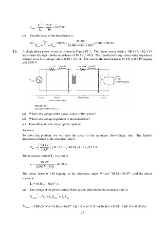
          2-2.   A single-phase power system is shown in Figure P2-1.  The power source feeds a 100-kVA 14/2.4-kV
                 transformer through a feeder impedance of 38.2 + j140 .  The transformer’s equivalent series impedance
                 referred to its low-voltage side is 0.10 + j0.4 .  The load on the transformer is 90 kW at 0.8 PF lagging
                 and 2300 V.


                 (a)  What is the voltage at the power source of the system?

                 (b)  What is the voltage regulation of the transformer?
                 (c)  How efficient is the overall power system?

                 SOLUTION
                 To solve this problem, we will refer the circuit to the secondary (low-voltage) side.  The  feeder’s
                 impedance referred to the secondary side is

                              2.4 kV   2
                        line         Z      j    38.2     140     1.12   j 4.11 
                               14 kV 
                 The secondary current I S   is given by

                              90 kW
                       I   S     2400 V 0.8     46.88 A
                                   

                 The power factor is 0.80 lagging,  so  the  impedance  angle     cos  1 0.8  36.87    , and the phasor
                 current is

                                        
                       I S    46.88     36.87  A
                 (a)  The voltage at the power source of this system (referred to the secondary side) is

                                         
                       V source    V   I S Z line    I S Z  EQ
                                 S

                      
                                                                                           
                               
                                                                       A 1.12 
                  V source   2400 0  V      36.87  46.88    j 4.11     46.88 36.87  A 0.10   j 0.40   
                                                           27
   28   29   30   31   32   33   34   35   36   37   38