
Page 36 - Solutions Manual to accompany Electric Machinery Fundamentals
P. 36
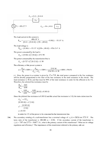
Z line 0.12 j 0.16
V 480 0 V Z 30 j 40
S load
The load current in this system is
480 0 V
I load j 0.16 0.12 30 j 40 9.562 53.13 A
The load voltage is
V 53.13 A 30 9.562 j 40 478 3.4 A
load
The power consumed by the load is
P 9.562 A 2 30 2743 W
load
The power consumed by the transmission line is
P line 8.727 A 2 0.12 11 W
The efficiency of the power system is
P P 2743 W
OUT 100% load 100% 100% 99.6%
P P P 2743 W 11 W
IN load line
2
(c) Since the power in a resistor is given by P I R , the total power consumed in the line resistance
will be directly proportional to the ratio of the line resistance to the total resistance in the circuit. The
load resistance is 30 , and that must be 99% of the total resistance in order for the efficient to be 1%.
Therefore, the referred line resistance must be
R line 0.01
R load 0.99
R 0.01 R 0.01 30 0.303
line
0.99 load 0.99
Since the referred line resistance is 0.303 and the actual line resistance is 3 , the turns ration must be
2
Z line aZ line
0.303 a 2
3
0.303
2
a
3
a 0.318
in order for 1% of the power to be consumed in the transmission line.
2-4. The secondary winding of a real transformer has a terminal voltage of vt() 282 .8 sin 377 t V . The
s
turns ratio of the transformer is 100:200 (a = 0.50). If the secondary current of the transformer is
. it () t 707 sin 377 36 .87 A , what is the primary current of this transformer? What are its voltage
s
regulation and efficiency? The impedances of this transformer referred to the primary side are
30