
Page 34 - Solutions Manual to accompany Electric Machinery Fundamentals
P. 34
source V 2576 3.0 V
Therefore, the voltage at the power source is
V 2576 3.0 V 14 kV 15.5 3.0 kV
source
2.4 kV
(b) To find the voltage regulation of the transformer, we must find the voltage at the primary side of the
transformer (referred to the secondary side) under these conditions:
V V I S Z EQ
P
S
2400 0 V 36.87 46.88 j 0.40 A 0.10 2415 0.3 V
P V
There is a voltage drop of 15 V under these load conditions. Therefore the voltage regulation of the
transformer is
2415 2400
VR 100% 0.63%
2400
(c) The overall efficiency of the power system will be the ratio of the output power to the input power.
The output power supplied to the load is P OUT = 90 kW. The input power supplied by the source is
P IN P OUT P LOSS P OUT 2 I R 90 kW 46.88 A 2 1.22 92.68 kW
P IN V source I S cos 2415 V 46.88 A cos 36.57 90.93 kW
Therefore, the efficiency of the power system is
P 90 kW
OUT 100% 100% 97.1%
P IN 92.68 kW
Note: Problem 2-3 was printed incorrectly in the first edition of this text. By
accident, a portion of Problem 2-4 was printed here instead of the appropriate
text. This should be fixed by the second printing of the book.
2-3. Consider a simple power system consisting of an ideal voltage source, an ideal step-up transformer, a
transmission line, an ideal step-down transformer, and a load. The voltage of the source is
V 480 0 V . The impedance of the transmission line is Z 3 4 j , and the impedance of the
S line
load is Z load 30 j 40 .
(a) Assume that the transformers are not present in the circuit. What is the load voltage and efficiency
of the system?
(b) Assume that transformer 1 is a 1:5 step-up transformer, and transformer 2 is a 5:1 step-down
transformer. What is the load voltage and efficiency of the system?
(c) What transformer turns ratio would be required to reduce the transmission line losses to 1% of the
total power produced by the generator?
SOLUTION
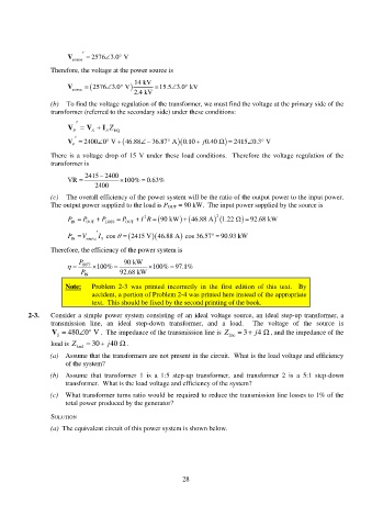
(a) The equivalent circuit of this power system is shown below.
28