
Page 38 - Solutions Manual to accompany Electric Machinery Fundamentals
P. 38
P V I cos 106.5 V 11.0 A cos 2.8 40.0
IN PP
P IN 106.5 V 11.0 A cos 42.8 860 W
The output power from this transformer is
P OUT V I cos 200 V 5 A cos 36.87 800 W
SS
Therefore, the transformer’s efficiency is
P 800 W
OUT 100% 100% 93.0%
P 860 W
IN
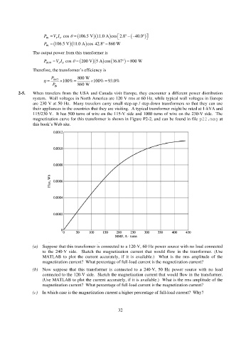
2-5. When travelers from the USA and Canada visit Europe, they encounter a different power distribution
system. Wall voltages in North America are 120 V rms at 60 Hz, while typical wall voltages in Europe
are 230 V at 50 Hz. Many travelers carry small step-up / step-down transformers so that they can use
their appliances in the countries that they are visiting. A typical transformer might be rated at 1-kVA and
115/230 V. It has 500 turns of wire on the 115-V side and 1000 turns of wire on the 230-V side. The
magnetization curve for this transformer is shown in Figure P2-2, and can be found in file p22.mag at
this book’s Web site.
(a) Suppose that this transformer is connected to a 120-V, 60 Hz power source with no load connected
to the 240-V side. Sketch the magnetization current that would flow in the transformer. (Use
MATLAB to plot the current accurately, if it is available.) What is the rms amplitude of the
magnetization current? What percentage of full-load current is the magnetization current?
(b) Now suppose that this transformer is connected to a 240-V, 50 Hz power source with no load
connected to the 120-V side. Sketch the magnetization current that would flow in the transformer.
(Use MATLAB to plot the current accurately, if it is available.) What is the rms amplitude of the
magnetization current? What percentage of full-load current is the magnetization current?
(c) In which case is the magnetization current a higher percentage of full-load current? Why?
32