
Page 35 - Solutions Manual to accompany Electric Machinery Fundamentals
P. 35
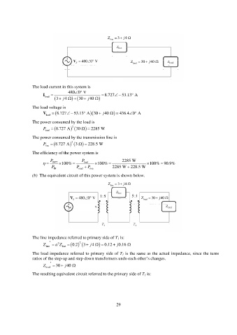
Z line 3 4 j
V 480 0 V Z 30 j 40
S load
The load current in this system is
480 0 V
I load j 3 4 30 j 40 8.727 53.13 A
The load voltage is
V 8.727 53.13 A 30 j 40 436.4 0 A
load
The power consumed by the load is
P 8.727 A 2 30 2285 W
load
The power consumed by the transmission line is
P line 8.727 A 2 3 228.5 W
The efficiency of the power system is
P P 2285 W
OUT 100% load 100% 100% 90.9%
P IN P load P line 2285 W 228.5 W
(b) The equivalent circuit of this power system is shown below.
Z line 3 4 j
V 480 0 V 1:5 5:1 Z 30 j 40
S load
The line impedance referred to primary side of T 1 is:
2 2
Z line a Z line 0.2 3 4 j 0.12 j 0.16
The load impedance referred to primary side of T 1 is the same as the actual impedance, since the turns
ratios of the step-up and step-down transformers undo each other’s changes.
Z load 30 j 40
The resulting equivalent circuit referred to the primary side of T 1 is:
29