
Page 124 - Instrumentation Reference Book 3E
P. 124
Elastic elements 109
Applied
force
(Rochelle salt quartz lead
zirconate titanate)
Bare
I OUtpUt
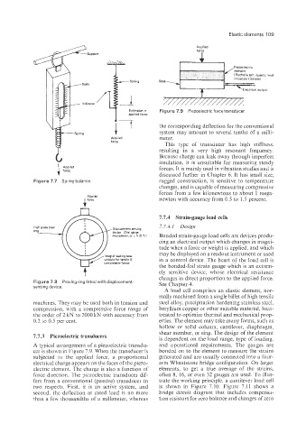
Extension a Figure 7.9 Piezoelectric force transducer
applied force
Applied i7 the corresponding deflection for the conventional
system may amount to several tenths of a milii-
meter.
force
This type of transducer has high stiffness,
resulting in a very high resonant frequency.
Because charge can leak away through imperfect
insulation, it is unsuitable for measuring steady
forces. It is mainly used in vibration studies and is
discussed further in Chapter 6. It has small size,
Figure 7.7 Spring balance. rugged construction, is sensitive to temperature
changes, and is capable of measuring compressive
forces from a few kilonewtons to about 1 mega-
newton with accuracy from 0.5 to 1.5 percent.
7.7.4 Strain-gauge load cells
- 7.7.4.1 Design
High grade steel
ring
Bonded strain-gauge load cells are devices produ-
cing an electrical output which changes in magni-
tude when a force or weight is applied, and which
may be displayed on a readout instrument or used
Integral loading boss
uitable for tensile & in a control device. The heart of the load cell is
the bonded-foil strain gauge which is an extrem-
ely sensitive device, whose electrical resistance
changes in direct proportion to the applied force.
Figure 7.8 Proving ring fitted with displacement. See Chapter 4.
sensing device.
A load cell comprises an elastic element, nor-
mally machined from a single billet of high tensile
machines. They may be used both in tension and steel alloy, precipitation hardening stainless steel,
compression, with a compressive force range of beryllium copper or other suitable material, heat-
the order of 2 kN to 2000 kN with accuracy from treated to optimize thermal and mechanica: prop-
0.2 10 0.5 pes cent. erties. The element may take many forms, such as
hollow or solid column, cantilever, diaphragm,
shear member, or ring. The design of the element
’7.7.3 Piezoelectric transducers
is dependent on the load range, type of loading,
A typical arrangement of a piezoelectric transdu- and operational requirements. The gauges are
cer is shown in Figure 7.9. When the transducer is bonded on to the element to measure the strains
subjected to the applied force, a proportional generated and are usually connected into a foour-
electrical charge appears on the faces of the piezo- arm Wheatstone bridge configuration. On larger
electric element. The charge is also a function of elements, to get a true average of the strains,
force direction. The 2iezoelectric transducer dif- often 8, 16, or even 32 gauges are used. To illus-
fers from a conventional (passive) transducer in trate the working principle, a cantilever load cell
two respects. First, it is an active system, and is shown in Figure 7.10. Figure 7.1 1 shows a
second, the deflection at rated load is no more bridge circuit diagram that includes compensa-
than a few thousandths of a millimeter, whereas tion resistors for zero balance and changes of zero