
Page 126 - Instrumentation Reference Book 3E
P. 126
Elastic elements 111
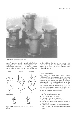
Figure 7.12 Compression load cells
ways of reducing the spring rates is to fit flexible varying stiffness due to varying pressure (see
couplings in the pipework, preferably in a hori- F and G in Figure 7.14). Where possible, entry
zontal mode, and after (for example) the dis- pipes should be free of contact with the vessel
charge valve so that they are not subject to (refer to H and I).
Normal Non-axial Sidedoading
7.7.4.3 Applicutions
W
Load cells have many applications including
weight and force measurement, weigh platforms,
process control systems, monorail weighing, belt-
weighers, aircraft, freight and baggage weighing,
and conversion of a mechanical scale to an elec-
tronic scale. Over the past few years, the indus-
trial weighing field has been dominated by load
cells because electrical outputs are ideal for local
and remote indication and to interface with
microprocessors and minicomputers.
A B C
SG=Strain gauger Key features of load cells are:
I (a) Load range 5N to 40MN.
(b) Accuracy 0.01 to 1.0 percent.
(c) Rugged and compact construction.
(d) No moving parts and negligible deflection
under load.
Correct Incorrect
A C (e) Hermetically sealed and thermal compensation.
Figure 7.13 Effects of normal, non-axial, and side- (0 High resistance to side-loads; withstands over-
loading. loads.