
Page 127 - Instrumentation Reference Book 3E
P. 127
112 Measurement of force
H I The foregoing has indicated some force-
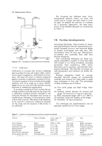
Incorrect corrsct
measurement methods. Others are many and
varied and no attempt has been made to cover
all types. To simplify the selection of a method
for a particular application, the main para-
meters of the methods discussed are summarized
in Table 7.1.
7.8 Further developments
Advancing technology, improvements in manu-
facturing techniques, and new materials have per-
adcell
mitted increased accuracy and improved design
of bonded strain-gauge load cells since their
introduction about 30 years ago. Microproces-
/I il" sor-enabled and controlled load cells have
n become ubiquitous.
Y New transducing techniques are being con-
Incorrect correct cisrnp
Figure 7.14 Examples of correct and incorrect fitments. stantly researched; a number of them have been
well studied or are being considered, including
gyroscopic force transducers, fiber optics,
7.7.4.4 Calibrutiori microwave cavity resonator, and thin-film trans-
ducing techniques. The thin-film techniques are
Calibration is a process that involves obtaining well documented and therefore are briefly dis-
and recording the load cell output while a direct cussed.
known input is applied in a well-defined environ- Pressure transducers based on vacuum-
ment. The load cell output is directly compared deposited thin-film gauges are commercially
against a primary or secondary standard of force. available and attempts are being made to apply
A primary standard of force includes dead-weight these techniques to load cells. The advantages
machines with force range up to about 500 kN; of these techniques are as follows:
higher forces are achieved with machines having
hydraulic or mechanical amplification. (a) Very small gauge and high bridge resist-
A secondary standard of force involves the use ance.
of high precision load cells and proving rings with (b) Intimate contact between the element and
a calibration standard directly traceable to the gauge. No hysteresis or creep of a glue line.
National Institute for Standards and Testing in (c) Wide temperature range (-200 "C to + 200 "C).
Gaithersburg, Maryland, or the equivalent stand- (d) Excellent long-term stability of the bridge.
ards in other countries. The choice of the standards (e) Suitability for mass production.
to be used for a particular calibration depends
on the range and the location of the device to The techniques are capital-intensive and are
be calibrated. generally suitable for low force ranges.
Table 7.1 Summary of main parameters of force-measuring methods
Method Tvpe of loading Accuracy % Size
(flpprox. )
Lever balance Static 0.001 to 150k Very high Bulky and heavy
Force-balance Static/dynamic 0.1 to 1 k Very high Bulky and heavy
Hydraulic load cell Statiddynamic 5k to 5M 0.25 to 1.0 Compact and stiff
Spring balance Static 0.1 to 10k Low Large and heavy
Proving ring Static 2k to 2M 0.2 to 0.5 Compact
Piezoelectric transducer Dynamic 5ktolM 0.5 to 1.5 Small
Strain-guage load cell Static/dynamic 5 to 40M 0.01 to 1.0 Compact and stiff