
Page 132 - Instrumentation Reference Book 3E
P. 132
Measurement of density using hydrostatic head 117
9 Overflow Inlet
Densii ’*
signal
Outlet (Relative density= p,) outlet
Figure 8.7 Density measurement with constant head
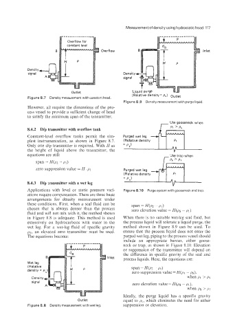
Figure 8.9 Density measurement with purge liquid
However, all require the dimensions of the pro-
cess vessel to provide a sufficient change of head
to satisfy the minimum span of the transmitter.
8.4.2 Dlp transmitter with overflow tank
Constant-level overflow tanks permit the sim-
plest instrumentation, as shown in Figure 8.7.
Only one dip transmitter is required. With H as
the height of liquid above the transmitter, the
equations are still:
span = H(p2 - PI)
zero suppression value = H . pi
8.4.3 Dlp transmitter with a wet leg
Applications with level or static pressure vari- Figure 8.1 0 Purge system with gooseneck and trap.
ations require compensation. There are three basic
arrangements for density measurement under
these conditions. First, when a seal fluid can be
chosen that is always denser than the process span = Wpz - PI)
zero elevation value = H(ps - PI 1
fluid and ill not mix with it, the method shown
in Figure 8.8 is adequate. This method is used When there is no suitable wet-leg seal fluid, but
extensively on hydrocarbons with water in the the process liquid will tolerate a liquid purge, the
wet leg. For a wet-leg fluid of specific gravity method shown in Figure 8.9 can be used. To
ps, an elevated zero transmitter must be used. ensure that the process liquid does not enter the
The equations become: purged wet leg, piping to the process vessel should
include an appropriate barrier, either goose-
neck or trap, as shown in Figure 8.10. Elevation
or suppression of the transmitter will depend on
the difference in specific gravity of the seal and
B 3 Inlet process liquids. Here, the equations are:
Wet leg
(Relative
span = H(p2 - PI)
zero suppression value = H(pl - ps),
when PI > ps
zero elevation value = H(ps - PI).
when PS > PI
Ideally, the purge liquid has a specific gravity
Outlet equal to PI, which eliminates the need for either
Figure 8.8 Densitymeasurement with wet leg suppression or elevation.