
Page 136 - Instrumentation Reference Book 3E
P. 136
Measurement of density using resonant elements 121
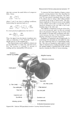
take into account the small effects of compressi- To measure the lower densities of gases, a more
bility. Hence sensitive sensing element than that described for
RD =(E) measurements on liquids is required. The Solar-
tron 7812 gas density transducer shown in Figure
(real) TP 8.16 achieves this by using a thin-walled cylinder
resonated in the hoop or radial mode. The max-
where T and P are close to ambient conditions. imum amplitude of vibration occurs at the middle
Substituting the equation leads to P of the cylinder with nodes at each end, and it is
therefore clamped at one end with a free node-
forming ring at the other end.
The cylinder is immersed in the gas whose den-
For most practical applications this leads to sity is to be measured, and it is thus not stressed
due to the pressure of the gas. Gas in contact with
the cylinder is brought into oscillation and effec-
tively increases the mass of the vibrating system,
thereby reducing its resonant frequency.
Thus, the signal from the density transducer pro- Oscillation is maintained electromagnetically by
vides an indication of the molecular weight or positioning drive and pick-up coils inside the cylin-
specific gravity of the sampled gas. der and connecting them to a maintaining ampli-
The measurement can be applied to almost any fier. The coils are mounted at right angles to each
gas provided that it is clean, dry, and non-corro- other to minimize stray coupling and phased so that
sive. The accuracy is typically 0.1 percent of the induced signal is proportional to the velocity,
reading and the repeatability 0.02 percent. thereby reducing the effect of viscous damping.
Access to
maintaining amplifier
I I lpllllal I IUU511 l!j
, External connections
Cable gland
n+*- Gas outlet
-r- - 9op filter (outlet)
Gas outlet path -- ...
211 filter (inlet)-& a:---*
tl.. '-W. -2.
-s, Filter element
Gas inlet - - Gas inlet path
Inspection port -
Spool body - - Excitation coil
- Embodied temperature sensor
Figure 8.1 6 Solartron 7812 gas density transducer. Courtesy, SolartronTransducers.