
Page 137 - Instrumentation Reference Book 3E
P. 137
122 Measurement of density
A low temperature coefficient is obtained by
constructing the cylinder from material having a
low temperature coefficient of expansion. The
cylinder wall thickness varies from 0.05 to
0.15 mm according to the required density range,
the corresponding density ranges varying from 0
to 60 kg/m3 and 40 to 400 kg/m3.
The relation between the time period of oscilla- for Calibration -
tion of the transducer and gas density p is given ga3e3 Valve B relief va ve
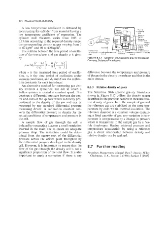
by Figure 8.17 Solartron 3096 specific gravity transducer.
Courtesy, SolartronTransducers.
where 7 is the measured time period of oscilla- difference between the temperature and pressure
tion, 70 is the time period of oscillation under of the gas in the density transducer and that in the
vacuum conditions, and do and K are the calibra- main stream.
tion constants for each transducer.
An alternative method for measuring gas den- 8.6.3 Relative density of gases
sity involves a cylindrical test cell in which a
hollow spinner is rotated at constant speed. This The Solartron 3096 specific gravity transducer
develops a differential pressure between the cen- shown in Figure 8.17 utilizes the density sensor
ter and ends of the spinner which is directly pro- described in the previous section to measure rela-
portional to the density of the gas and can be tive density of gases. In it, the sample of gas and
measured by any standard differential pressure the reference gas are stabilized at the same tem-
measuring device. A calibration constant con- perature by coils within thermal insulation. The
verts the differential pressure to density for the reference chamber is a constant volume contain-
actual conditions of temperature and pressure in ing a fixed quantity of gas; any variation in tem-
the cell. perature is compensated by a change in pressure
A sample flow of gas through the cell is which is transmitted to the sample gas by a flex-
induced by connecting it across a small restriction ible diaphragm. Having achieved pressure and
inserted in the main line to create an adequate temperature equalization by using a reference
pressure drop. The restriction could be deter- gas, a direct relationship between density and
mined from the square root of the differential relative density can be realized.
pressure across the orifice plate multiplied by
the differential pressure developed in the density
cell. However, it is important to ensure that the 8.7 Further reading
flow of the gas through the density cell is not a
significant proportion of the total flow. It is also Petroleum Measuyenient Manual, Part 7: Density, Wiley,
important to apply a correction if there is any Chichester, U.K., Section 2 (1984); Section 1 (1985)