
Page 134 - Instrumentation Reference Book 3E
P. 134
Measurement of density using resonant elements 119
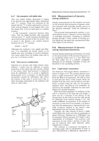
8.4.7 Dlp transmitter with bubble tubes 8.5 Measurement of density
This very simple system, illustrated in Figure using radiation
8.14, involves two open-ended tubes, terminated
with ‘V notches. These are immersed in the Density measurements by this method are based
liquid with the ‘‘V> notches separated by a known on the principle that absorption of gamma radia-
fixed vertical distance H and purged with a low tion increases with increasing specific gravity of
but steady flow of air (or inert gas) at a suitable the material measured. These are discussed in
pressure. Part 3.
A dlp transmitter connected between these The principal instrumentation includes: a con-
tubes, with the higher-pressure side associated stant gamma source, a detector, and an indicating
with the lower ”V” notch, measures the difference or recording instrument. Variations in radiation
Ap in hydrostatic pressure at the two points. This passing through a fixed volume of flowing pro-
is equal to the density x the vertical distance cess liquid are converted into a proportional elec-
between the two “V” notches: trical signal by the detector.
density = Ap/H
8.6 Measurement of densit
Although this method is very simple and effec- using resonant elements
tive, it is unsuitable for closed vessels or for
liquids that may crystallize or involve precipita- Several density-measuring instruments are based
tion which might block the bubble tubes and so on the measurement of the resonant frequency of
give rise to erroneous results. an oscillating system such as a tube filled with
the fluid under test or a cylinder completely
8.4.8 Other process considerations immersed in the medium. Examples of each are
described in the succeeding sections.
Agitation in a process tank where density meas-
urement is made must be sufficient to ensure
uniformity of the liquid. But the velocity of fluid 8.6.1 Liquid density measurement
at the points where head pressure is measured The Solartron 7835 liquid density transducer is
must be sufficiently Bow to avoid a significant shown in Figure 8.15. The sensing element com-
measurement error. Locations of side-mounted prises a single smooth-bore tube through which
transmitters should be sufficiently high above flows the fluid to be measured. The tube is fixed
the bottom of the tank to avoid errors due to at each end into heavy nodal masses which are
them becoming submerged in the sediment that isolated from the outer case by bellows and liga-
tends to collect there. ments. Located along the tube are the electro-
magnetic drive and pick-up coil assemblies. In
operation, the amplifier maintains the tube oscil-
lating at its natural frequency.
Since the natural frequency of oscillation of the
tube is a function of the mass per unit length, it
must also be a function of the density of the
flowing fluid. It also follows that the tube should
be fabricated from material having a low and
stable coefficient of expansion. If for reasons of
corrosion or wear this is not possible. it is impor-
tant that the temperature is measured and a sui-
table correction applied to the density value
determined from the resonant frequency.
Bubble
tube Typically, the tube vibrates at about 1.3 kHz
air (when filled with water) and with an amplitude of
SUPPlV about 0.025 mm. Densities up to 3000 kg/m3 can
be measured with an accuracy of 0.2 kg/m3 and a
repeatability of 0.02 kg/m3. This contrasts with
accuracies of only about 1 percent of span that
can be achieved with other methods, unless
extreme care is taken.
The response is continuous throughout its
operating range with no adjustments of span or
Figure 8.14 D/p cell with bubble tubes. zero. Recalibration is effected by adjustment of