
Page 133 - Instrumentation Reference Book 3E
P. 133
118 Measurement of density
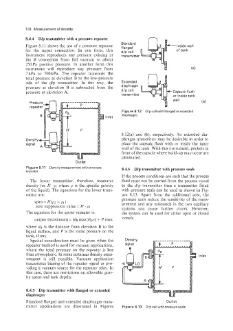
8.4.4 Dlp transmitter with a pressure repeater
Figure 8.11 shows the use of a pressure repeater
for the upper connection. In one form, this
instrument reproduces any pressure existing at
the B connection from full vacuum to about
250Pa positive pressure. In another form this
instrument will reproduce any pressure from
7kPa to 700kPa. The repeater transmits the
total pressure at elevation B to the low-pressure
side of the d/p transmitter. In this way, the
pressure at elevation B is subtracted from the
pressure at elevation A.
or inside tank
( b)
Inlet diaphragm.
8.12(a) and (b), respectively. An extended dia-
phragm transmitter may be desirable in order to
place the capsule flush with or inside the inner
wall of the tank. With this instrument, pockets in
front of the capsule where build-up may occur are
eliminated.
Outlet
Figure 8.11 Density measurement with pressure 8.4.6 Dlp transmitter with pressure seals
repeater.
If the process conditions are such that the process
The lower transmitter, therefore, measures fluid must not be carried from the process vessel
density (or H . p, where p is the specific gravity to the d/p transmitter then a transmitter fitted
of the liquid). The equations for the lower trans- with pressure seals can be used as shown in Fig-
mitter are: ure 8.13. Apart from the additional cost, the
span = H(p? -, PI 1 pressure seals reduce the sensitivity of the meas-
urement and any mismatch in the two capillary
zero suppression value = H . p1 systems can cause further errors. However,
The equation for the upper repeater is: the system can be used for either open or closed
output (maximum) = (GIB max)l(p?) + P max vessels.
where CEB is the distance from elevation B to the
liquid surface, and P is the static pressure on the
tank, if any.
Special consideration must be given when the
repeater method is used for vacuum applications,
where the total pressure on the repeater is less
than atmospheric. In some instances density meas- Inlet
urement is still possible. Vacuum application
necessitates biasing of the repeater signal or pro-
viding a vacuum source for the repeater relay. In
this case, there are restrictions on allowable grav-
ity spans and tank depths.
8.4.5 Dlp transmitter with flanged or extended
diaphragm
Standard flanged and extended diaphragm trans- Outlet
mitter applications are illustrated in Figures Figure 8.13 D/pcell with pressureseals.