
Page 130 - Instrumentation Reference Book 3E
P. 130
Measurement of density using buoyancy 115
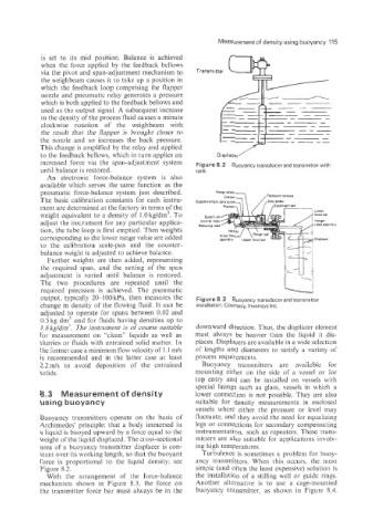
is set to its mid position. Balance is achieved Transmitter m
when the force applied by the feedback bellows
via the pivot and span-adjustment mechanism to
the weighbeam causes it to take up a position in
which the feedback loop comprising the flapper
nozzle and pneumatic relay generates a pressure
which is both applied to the feedback bellows and ___
used as the output signal. A subsequent increase --
in the density of the process fluid causes a minute -_
--
clockwise rotation of the weighbeani with --
the result that the flapper is brought closer to
the nozzle and so increases the back pressure.
This change is amplified by the relay and applied
to the feedback bellows: which in turn applies an Displacer'
increased force via the span-adjustment system Figure 8.2 Buoyancy transducerandtransmitter with
until balance is restored. tank.
An electronic force-balance system is also
available which serves the same function as the
pneumatic force-balance system just described. Rsnse wheel
,,,",,, 3 ,Feedback bellows
The basic calibration constants for each instru-
ment are determined at the factory in terms of the
weight equivalent to a density of 1 .O kg/dm3. To
adjust the instrument for any particular applica-
tion, the tube loop is first emptied. Then weights
corresponding to the lower range value are added
to the calibration scale-pan and the counter-
balance weight is adjusted to achieve balance.
Further weights are then added, representing
the required span, and the setting of the span
adjustment is varied until balance is restored.
The two procedures are repeated until the
required precision is achieved. The pneumatic
output, typically 20-100 kPa, then measures the Figure 8.3 Buoyancy transducer and transmittel
change in density of the flowing fluid. It can be installation. Courtesy, lnvensys Inc.
adjusted to operate for spans between 0.02 and
0.5kg dm: and for fluids having densities up to
1.6 kg/dm". The instrument is of course suitable downward direction. Thus, the displacer element
for measurement on "'clean" liquids as well as must always be heavier than the liquid it dis-
slurries or fluids with entrained solid matter. In places. Displacers are available in a wide selection
the former case a minimum flow velocity of 1.1 m/s of lengths and diameters to satisfj a variety of
is recommended and in the latter case at least process requirements.
7.2ds to avoid deposition of the entrained Buoyancy transmitters are available for
solids. mounting either on the side of a vessel or for
top entry and can be installed on vessels with
special linings such as glass, vessels in which a
Measurement of density lower connection is not possible. They are also
using buoyancy suitable for density measurements in enclosed
vessels where either the pressure or level may
Buoyancy transmitters operate on the basis of fluctuate, and they avoid the need for equalizing
Archimedes' principle: that a body immersed in legs or connections for secondary compensating
a liquid is buoyed upward by a force equal to the instrumentation, such as repeaters. These trans-
weight of the liquid displaced. The cross-sectional mitters are also suitable for applications involv-
area of a buoyancy transmitter displacer is con- ing high temperatures.
stant over its working length, so that the buoyant Turbulence is sometimes a problem for buoy-
force is proportional to the liquid density; see ancy transmitters. When this occurs, the most
Figure 8.2. simple (and often the least expensive) solution is
With the arrangement of the force-balance the installation of a stilling well or guide rings.
mechanism shown in Figure 8.3, the force on Another alternative is to use a cage-mounted
the transmitter force bar must always be in the buoyancy transmitter, as shown in Figure 8.4.