
Page 125 - Instrumentation Reference Book 3E
P. 125
110 Measurement of force
Figure 7.12 shows some commercially available
/ 1 (Strain gauges) Applied compression load cells that have been successfully
used for monitoring the tension in the mooring
?’G2
force
legs of a North Sea platform.
7.7.4.2 Selection and installation
There are five basic types of cell on the market:
compression, tension, universal (both compres-
sion and tension), bending, and shear. The main
Steel factors influencing the selection of cell type are:
G4 element
(a) The ease and convenience (and hence the
cost) of incorporating a cell into the weigher
structure.
(b) Whether the required rated load and accur-
Figure 7.1 0 Cantilever load cell acy can be obtained in the type of cell.
2 RJ environmental protection and a wide operating
Other considerations include low profile,
Input overload capacity, resistance to side-loads,
temperature range.
To retain its performance, a cell should be
REI
correctly installed into the weigher structure. This
means the structure of the weigher, such as vessel,
bin, hopper, or platform, is the governing factor in
the arrangement of the load cells. The supporting
structure is also to be considered since it will
carry the full weight of the vessel and contents.
Difficulties caused by misapplication leading to
1 Output rationalizatim (a) A non-axial load is applied.
poor performance and unreliability fall into three
main headings:
(b) Side-loads are affecting the weight reading.
G1-4
Gauger
Zero balance
RZ
(c) Free-axial movement of the load is restricted.
RS
Zero temp. compensation
RZT
Rst
Sensitivity temp.
Figure 7.13 shows how normal, non-axial, and
compensation
side-loading affects a column stress member.
Input
Under normal loading conditions (A) the active
strain gauges go into equal compression; how-
ever, under non-axial (B) or side-loading (C) con-
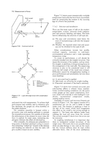
Figure 7.11 Load cell bridge circuit with compensation
resistors. ditions, asymmetrical compression results,
causing readout errors.
Examples of correct and incorrect fitments are
and sensitivity with temperature. To achieve high shown in Figure 7.14. The support bracket D is
performance and stability and to minimize glue cantilevered out too far and is liable to bend
line thickness, the gauges are often installed on under load. The bracket is applying a load to
flat-sided elements. the side of the vessel, which itself exaggerates
The complete assembly is housed within a this effect as the vessel is not strong enough to
protective case with sealing sufficient to exclude support it. The beam also deflects under load,
the external environment, but capable of allowing rotating the load cell away from the vertical.
the deformation of the element to occur when the The correct example E shows how the errors can
force is applied. In some cases, restraining dia- be overcome.
phragms minimize the effect of side-loading. In weighing installations it is important that
After assembly, the elements are subjected to a there is unimpeded vertical movement of the
long series of thermal and load cycling to ensure weigh vessel. Obviously this is not possible where
that remaining “locked-up’’ stresses in the element there are pipe fittings or stay rods on the vessel,
and bonding are relieved, so that the units will but the vertical stiffness must be kept within
give excellent long-term zero stability. allowable limits. One of the most satisfactory