
Page 142 - Instrumentation Reference Book 3E
P. 142
126 Measurement of pressure
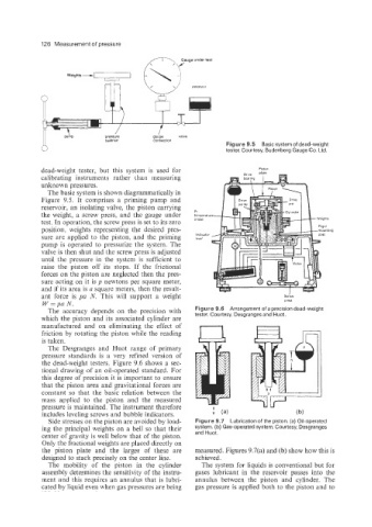
Figure 9.5 Basic system of dead-weight
tester. Courtesy, Budenberg Gauge Co. Ltd.
dead-weight tester, but this system is used for PlStO"
calibrating instruments rather than measuring
unknown pressures.
The basic system is shown diagrammatically in
Figure 9.5. It comprises a priming pump and
reservoir, an isolating valve, the piston carrying
the weight, a screw press, and the gauge under PI
ternperatu
test. In operation, the screw press is set to its zero probe
position, weights representing the desired pres-
sure are applied to the piston, and the priming Indicator
IkWC
pump is operated to pressurize the system. The
valve is then shut and the screw press is adjusted
until the pressure in the system is sufficient to
raise the piston off its stops. If the frictional
forces on the piston are neglected then the pres-
sure acting on it is p newtons per square meter,
and if its area is a square meters, then the result-
ant force is pa N. This will support a weight Screw
W =pa N. press
The accuracy depends on the precision with Figure 9.6 Arrangement of a precision dead-weight
which the piston and its associated cylinder are tester Courtesy, Desgranges and Huot
manufactured and on eliminating the effect of
friction by rotating the piston while the reading
is taken.
The Desgranges and Huot range of primary
pressure standards is a very refined version of
the dead-weight testers. Figure 9.6 shows a sec-
tional drawing of an oil-operated standard. For
this degree of precision it is important to ensure
that the piston area and gravitational forces are
constant so that the basic relation between the
mass applied to the piston and the measured
pressure is maintained. The instrument therefore
includes leveling screws and bubble indicators.
Side stresses on the piston are avoided by load- Figure 9.7 Lubrication of the piston. (a) Oil-operated
ing the principal weights on a bell so that their system. (b) Gas-operated system. Courtesy, Desgranges
center of gravity is well below that of the piston. and Huot.
Only the fractional weights are placed directly on
the piston plate and the larger of these are measured. Figures 9.7(a) and (b) show how this is
designed to stack precisely on the center line. achieved.
The mobility of the piston in the cylinder The system for liquids is conventional but for
assembly determines the sensitivity of the instru- gases lubricant in the reservoir passes into the
ment and this requires an annulus that is lubri- annulus between the piston and cylinder. The
cated by liquid even when gas pressures are being gas pressure is applied both to the piston and to